Installation Guide TracVision M7 TracVision M7 Switchplate Configuration
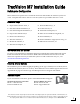
TracVision M7 Installation Guide Switchplate Configuration These instructions explain how to install the TracVision M7 satellite TV antenna system on a vessel. Complete instructions on how to use the system are provided in the User’s Guide. Installation Steps 1. Inspect Parts and Get Tools, 3 9. Wire the Receiver(s), 11 2. Plan the Antenna Installation, 4 10. Connect Power, 12 3. Plan the Switchplate Installation, 5 11. Mount the Switchplate, 13 4. Prepare the Antenna Site, 6 12.
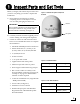
1 Inspect Parts and Get Tools Before you begin, follow these steps to make sure you have everything you need to complete the installation. Figure 1: TracVision M7 System Components Antenna a. Unpack the box and ensure it contains everything shown on the Kitpack Contents List. Save the packaging for future use. Radome IMPORTANT! Always lift the antenna by the baseplate and never by the radome or any portion of the internal antenna assembly (see Figure 1). Baseplate b.
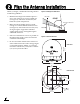
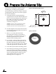
2 Plan the Antenna Installation Before you begin, consider the following antenna installation guidelines: • • Figure 4: Blockage from Obstruction Minimize blockage. The antenna requires a clear view of the sky to receive satellite TV (see Figure 4). The fewer obstructions, the better the system will perform. Make sure the mounting surface is wide enough to accommodate the antenna’s base (see Figure 5).
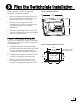
3 Plan the Switchplate Installation Before you begin, consider the following switchplate installation guidelines: • Select a switchplate mounting location in a dry, well-ventilated area belowdecks away from any heat sources or salt spray. • Be sure to leave enough room at the switchplate’s rear panel for connecting the cables (see Figure 6 for switchplate dimensions). • Figure 6: Switchplate Dimensions 4.39" (111.5 mm) 2.96" (75.
4 Prepare the Antenna Site Once you have identified a suitable antenna mounting site, according to the guidelines provided in Step 2, follow these steps to drill the mounting holes and cable access hole to prepare the site for installation. a. Unfold the antenna mounting template (supplied in the Customer Welcome Kit) and place it onto the mounting surface. Make sure the “FWD” (forward) arrow points toward the bow and is parallel to the vessel’s centerline (see Figure 8).
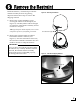
5 Remove the Restraint Inside the antenna, a foam block prevents the antenna assembly from moving during shipment. Follow these steps to remove this shipping restraint. Figure 10: Removing the Radome a. Remove the six #10-32 Phillips screws securing the radome to the baseplate (see Figure 10). Carefully lift the radome straight up until clear of the antenna assembly and set it aside in a safe place. TIP: If you keep the radome topside, secure it with a lanyard to prevent it from falling overboard.
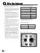
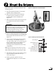
6 Wire the Antenna Follow these steps to connect the data, power, and RF cables to the antenna. a. First determine the number of RF coax cables required for your particular installation (see Figure 12). (See Figure 13 to determine the type of cable required.) b. Route the data, power, and RF cables belowdecks through the 3" (80 mm) cable access hole. Leave an adequate service loop, approximately 8" (20 cm) of slack, in the cables for easy serviceability.
7 Mount the Antenna Follow these steps to mount the antenna to the mounting surface. Figure 15: Forward Arrow in Antenna Baseplate a. Place the antenna baseplate over the holes drilled in the mounting surface. b. Make sure the forward arrow inside the baseplate points toward the bow and is parallel to the vessel’s centerline (see Figure 15). c. Make sure the four holes in the baseplate line up with the four holes in the mounting surface.
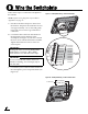
8 Wire the Switchplate Follow these steps to connect the switchplate to the antenna. Figure 17: Switchplate Wiring - Antenna Data Cable NOTE: System wiring diagrams are provided in Appendix D on page 27. a. First dress the data and power cables from the antenna. Strip back the insulation of each wire approximately 1/4" (6 mm) and gently twist each wire to ensure a good electrical connection. b. Connect the data cable from the antenna to the terminal board on the back of the switchplate (see Figure 17).
9 Wire the Receiver(s) In Step 6, you routed the RF coax cable(s) from the antenna, through the cable access hole, and into the vessel. Follow these steps to connect the RF coax cable(s) to the customer’s satellite TV receiver(s). Figure 19: Wiring the Receivers to the Antenna Antenna IMPORTANT! If you wish to connect three or more receivers to the antenna, see Appendix A on page 21. a. If you are connecting two receivers to the TracVision system, decide which receiver will be the primary receiver.
10 Connect Power Follow these steps to connect power. The switchplate supplies power to the antenna. a. Before you begin, disconnect vessel power. Figure 20: Switchplate Wiring - Vessel Power Cable Vessel Power Ground 11-16 VDC CAUTION For your own safety, disconnect vessel power and make sure the circuit is dead before you connect any power wires. b. Connect a power cable to 12 VDC vessel power (for cable specifications, see Figure 3 on page 3).
11 Mount the Switchplate In Step 3, you identified a suitable mounting location for the switchplate and cut out the mounting hole in the mounting surface. Now follow these steps to mount the switchplate. a. Fit the switchplate assembly into the mounting hole until it is flush with the mounting surface. Figure 21: Mounting the Switchplate Front Cover Switchplate Mounting Surface b. Drill four 5/32" (4 mm) holes in the countersunk settings in the switchplate’s support frame (see Figure 21). c.
12 Enter Your Latitude & Longitude Follow these steps to enter your vessel’s latitude and longitude into the antenna. Figure 22: Direction to Satellite Depends on Your Location NOTE: The antenna will use your position information to speed up satellite acquisition. If the antenna knows where you are, it knows where it should start looking for the satellite (see Figure 22). In addition, for a linear system, the antenna will use your position information to calculate the correct LNB skew angle.
12 Continued... c. Ensure the antenna has a clear, unobstructed view of the sky. Figure 25: Antenna Data Scrolling in Window d. Apply power to the satellite TV receiver(s) and the switchplate (see Figure 23 on page 14). Wait two minutes for system startup. e. Data should now be scrolling in your HyperTerminal window (see Figure 25). If no data appears, check your connections and make sure you’re using the right COM port.
13 Select Satellites Follow these steps to set up the system for the desired pair of satellites. Figure 26: Technician Programming the Antenna IMPORTANT! The antenna is programmed at the factory for the following default satellite pair: Circular: DSS_101 & DSS_119 (DIRECTV) Linear: ASTRA & HOTBIRD If these are the customer’s desired satellites, you may skip this step. Enter the following commands via Windows HyperTerminal or KVH Flash Update Wizard: a. Type HALT then press Enter. b.
14 Set the LNB Skew Angle (Linear only) Follow these steps to set the antenna’s linear LNB to the correct skew angle for your selected satellite and vessel position. a. Using HyperTerminal or KVH Flash Update Wizard, type SKEWANGLE then press Enter. Note the reported skew angle. TIP: The SKEWANGLE command provides the correct skew angle for the currently selected satellite only. If a pair of satellites is installed, you might wish to set an average skew instead.
15 Educate the Customer The installation process is complete! Figure 29: Example of Satellite Blockage Before you depart the vessel, test the system to verify the antenna works properly. Then give the Customer Welcome Kit to the customer and explain how to use the system. Also be sure the customer understands the following: • Keep the radome installed on the antenna at all times. The radome protects the antenna’s moving parts from wind, rain, and debris.
Appendices This section provides supplemental instructions for advanced configurations. It also provides system wiring diagrams and a switchplate mounting template. Contents A. Wiring 3+ Receivers, 21 B. Satellite Library, 23 C. User-Defined Satellites, 24 D.
A Wiring 3+ Receivers Appendix IMPORTANT! Only antennas equipped with a circular dual LNB or a linear quad LNB can support more than two receivers. Antennas equipped with a linear dual LNB support only two receivers. Figure 30: Multiswitch Wiring - Antenna with Circular Dual LNB Antenna with Circular Dual LNB Antenna (North American systems only) To connect three or more receivers, follow these steps to install an active (powered) multiswitch between the antenna and the receivers.
A Continued... Antenna with Linear Quad LNB Figure 31: Receiver Wiring - Antenna with Linear Quad LNB (European systems only) Follow these steps to connect three or four receivers directly to the antenna. Antenna NOTE: If you need to connect more than four receivers to the TracVision system, install an active multiswitch that generates a 22 KHz tone (such as Spaun model 5602NF - KVH part #19-0413). Connect the multiswitch in accordance with the manufacturer’s instructions. Power Data Switchplate + 1.
B Satellite Library Appendix The TracVision antenna can track a variety of DVB-compatible and DSS (DIRECTV) satellites. Most popular satellites are programmed in the antenna’s library (see the tables below). North America Europe Standard Circular Dual LNB Required Linear Dual or Linear Quad LNB Required Satellite, Longitude Name in Library Satellite Name in Library DIRECTV, 72°W DSS_72 Astra 1, 19.2°E ASTRA1 DIRECTV, 101°W DSS_101 Astra 2N, 28.
C User-Defined Satellites The satellite library in the TracVision antenna includes two slots for user-defined satellites (USER 1 and USER 2). You can program one or both of these library slots for any satellite you wish that is not already set up in the library.
C Continued... Enter the following commands via Windows HyperTerminal or KVH Flash Update Wizard. 1. Type HALT then press Enter. 2. Type DEBUGON then press Enter. 3. Type the following SATCONFIG command then press Enter. Italics indicate a variable field (see Figure 33 for definitions). SATCONFIG,USERA,B,C,D,E 4. Type @DEBUGON then press Enter. 5. Type the following @SATCONFIG command then press Enter. Italics indicate a variable field (see Figure 34 for definitions). @SATCONFIG,F,G,H,I,J,K,L,M,N 6.
C Continued... Example - Linear Satellite Example - Circular Satellite The following is an example of programming a linear user-defined satellite (USER 1). The following is an example of programming a circular user-defined satellite (USER 1). Satellite Name: YOURSAT 123 at 7°W Satellite Name: YOURSAT 456 at 122°W Transponder Data Value Horizontal High Transponder Data Value Right Frequency 11.966 GHz Frequency 12.
D Wiring Diagrams This appendix provides system wiring diagrams for the following receiver configurations: • One or two receivers • Three or more receivers (circular) • Three or more receivers (linear quad) Appendix IMPORTANT! The wiring diagrams on the following pages are intended as a quick reference only. Be sure to follow the complete wiring instructions provided earlier in this manual.
D Continued...
D Continued...
D Continued...
.16" (4 mm) 2.36" (60 mm) 3.19" (81 mm) Panel Cutout 3.82" (97 mm) .32" (8 mm) (2.25 mm) 2.
KVH Industries, Inc. 50 Enterprise Center Middletown, RI 02842-5279 U.S.A. Phone: +1 401 847-3327 Fax: +1 401 849-0045 E-mail: info@kvh.com Internet: www.kvh.com © Copyright 2006 KVH Industries Inc. KVH Europe A/S Kokkedal Industripark 2B 2980 Kokkedal Denmark Phone: +45 45 160 180 Fax: +45 45 160 181 E-mail: info@kvh.dk Internet: www.kvh.com KVH and TracVision are registered trademarks of KVH Industries Inc.