Installation Guide TracVision M9 TracVision M9 Standard Configuration
TracVision® M9 Installation Guide These instructions explain how to install the TracVision M9 satellite TV antenna system on a vessel. Complete instructions on how to use the system are provided in the User’s Guide. Installation Steps 1. Inspect Parts and Get Tools .......................3 8. Wire the Receiver(s) and MCU................10 2. Plan the Antenna Installation ....................4 9. Connect Power...........................................12 3. Plan the MCU Installation.....................
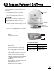
1 Inspect Parts and Get Tools Before you begin, follow these steps to make sure you have everything you need to complete the installation. Figure 1 TracVision M9 Antenna Radome a. Unpack the box and ensure it contains everything shown on the Kitpack Contents List. Save the packaging for future use. IMPORTANT! Always lift the antenna by the baseplate and never by the radome or any portion of the internal antenna assembly (see Figure 1). Baseplate b.
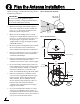
2 Plan the Antenna Installation Before you begin, consider the following antenna installation guidelines: Figure 4 Blockage from Obstruction -20° to 85° Look Angle IMPORTANT! Be sure to follow the guidelines below. Damage caused by an improper installation is not covered under KVH warranty. • • Make sure the mounting surface is wide enough to accommodate the antenna’s base (see Figure 5). Also make sure it is flat, level, strong enough to support the antenna’s weight (85 lbs, 38.
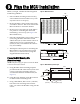
3 Plan the MCU Installation Before you begin, consider the following MCU installation guidelines: • Select an MCU mounting location in a dry, well-ventilated area belowdecks away from any heat sources or salt spray. • Be sure the MCU’s front panel will be easily accessible to the user. The owner will use the MCU’s buttons to control the antenna. • Be sure to leave enough room at the MCU’s rear panel for connecting the cables and maintaining a service loop (see Figure 6 for MCU dimensions).
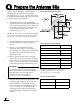
4 Prepare the Antenna Site Once you have identified a suitable antenna mounting site, according to the guidelines provided in Step 2 on page 4, follow these steps to drill the mounting holes and cable access hole to prepare the site for installation. Figure 8 Antenna Mounting Holes Layout a. Unfold the antenna mounting template (supplied in the Customer Welcome Kit) and place it onto the mounting surface.
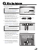
5 Wire the Antenna Follow these steps to connect the data/power and RF cables to the antenna. Figure 11 Antenna Connectors IMPORTANT! If you wish to route the cables through the bottom of the antenna’s baseplate, rather than connecting at the side, see Appendix A on page 23 for supplemental instructions. a. Route the data/power and RF cables belowdecks through the cable access hole. Leave an adequate service loop, approximately 8" (20 cm) of slack, in the cables for easy serviceability.
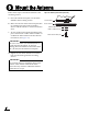
6 Mount the Antenna Follow these steps to mount the antenna to the mounting surface. Figure 15 Mounting the Antenna (side view) 10 mm max. a. Place the antenna baseplate over the holes drilled in the mounting surface. b. Make sure the four holes in the baseplate line up with the four holes in the mounting surface and the antenna’s connectors face the stern. c.
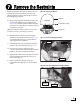
7 Remove the Restraints Inside the antenna, three heavy-duty tie-wraps prevent the antenna assembly from moving during shipment. Follow these steps to remove these shipping restraints. a. Remove the eight #10-32 Phillips-head screws securing the radome to the baseplate (see Figure 16). Carefully lift the radome straight up until clear of the antenna assembly and set it aside in a safe place.
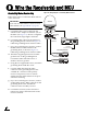
8 Wire the Receiver(s) and MCU Circular/Sky Mexico Version Only Figure 19 Wiring Diagram - Circular/Sky Mexico Version Follow these steps to connect the MCU and one or two receivers. IMPORTANT! Antenna If you wish to connect three or more receivers to the antenna, see Appendix B on page 25. a. Connect the data/power cable from the antenna to the “Output to Antenna” jack on the MCU (see Figure 19). Do not overtighten the connection; finger-tight is sufficient. b.
8 Continued Wire the Receiver(s) and MCU Linear Quad Version Only Figure 20 Wiring Diagram - Linear Quad Version Follow these steps to connect the MCU and up to four receivers. IMPORTANT! Antenna If you wish to connect three or more receivers to the antenna, see Appendix B on page 25. a. Connect the data/power cable from the antenna to the “Output to Antenna” jack on the MCU (see Figure 20). Do not overtighten the connection; finger-tight is sufficient.
9 Connect Power Follow these steps to connect power to the MCU. The MCU supplies power to the antenna. Figure 21 Ferrite Coil Clamped onto Power Cable Ferrite Coil a. Before you begin, disconnect vessel power. CAUTION For your own safety, disconnect vessel power and make sure the circuit is dead before you connect any power wires. b. Connect a power cable to 24 VDC (2.5 amps continuous) vessel power (for power cable specifications, see Figure 3 on page 3).
10 Mount the MCU In Step 3 on page 5, you identified a suitable MCU mounting location. Now follow these steps to mount the MCU using one of the following options: Option 1 - Velcro mount to a horizontal surface Figure 24 Velcro Mounting Fabric Strip (x4) Option 2 - Flush mount to a vertical surface Option 1 - Velcro Mount Hook Disk (x4) a. Clean the bottom of the MCU and the mounting surface using a mild detergent. b.
11 Select Satellites Follow these steps to turn on the system and select satellites for tracking. Figure 27 Install Satellite Menu a. Ensure the antenna has a clear, unobstructed view of the sky. Trac k ing S at B Satellite M e n u S at A C b. Apply power to the receiver(s), TV(s), and MCU. Wait two minutes for system startup. c. Press the center MENU button on the MCU to access the Install Satellite menu (see Figure 27). d. At “Install Satellite?”, press YES. e.
12 Calibrate the Internal Sensor The antenna’s internal compass sensor is calibrated at the factory for a perfect-world environment. However, hard and soft iron effects on your vessel can distort the magnetic field around the antenna, causing errors in the sensor’s reported heading. To compensate for these magnetic distortions, follow these steps to calibrate the internal sensor. Turn On Autocalibration Follow these steps to turn on the system’s Autocalibration function.
12 Continued Calibrate the Internal Sensor d. Steer the vessel at a slow, steady speed through a complete circle that takes at least two minutes to complete (see Figure 30). Use the heading you noted in Step c to confirm when you have completed a full circle. Figure 30 Running Autocalibration 2 Minutes Check the Calibration Score Once you have completed the circle, follow these steps to check the calibration “score.” 1 Minute, 30 Seconds 30 Seconds a.
13 Run Two Check Switch Tests If you set up the TracVision M9 system for DISH Network or Bell TV service, follow the steps below to run the receiver’s Check Switch test twice. NOTE: If you are connecting multiple receivers, repeat this process for each additional receiver. Connect each receiver, one at a time, to the RF1 cable and perform the steps below. Then, once you have completed this process for each receiver, you can reconnect them as desired. a. Dock the vessel in a blockage-free area in calm water.
14 Educate the Customer The installation process is complete! Figure 37 Example of Satellite Blockage Before you depart the vessel, test the system to verify the antenna works properly. Then give the Customer Welcome Kit to the customer and explain how to use the system. Also be sure the customer understands the following: • Keep the radome installed on the antenna at all times. The radome protects the antenna’s moving parts from wind, rain, and debris.
Appendices This section provides supplemental instructions for special or advanced configurations. It also provides system wiring diagrams and a mounting template for the belowdecks equipment. Contents A. Bottom Cable Entry Kit.................................................... 21 B. Connecting Additional Receivers .................................. 25 C. Clearing the Calibration Score........................................ 29 D. MCU Flush Mounting Template ....................................
A Bottom Cable Entry Kit If you wish to route the system cables through the bottom of the antenna’s baseplate, rather than connect the cables at the side of the baseplate, follow these steps to modify the antenna for bottom cable entry. Figure 38 shows the relevant parts of the antenna baseplate; refer to this figure throughout the procedure. Appendix Figure 38 Interior Baseplate (Antenna Not Shown) Cable Brackets Alternate Location for Cable PCB Remove the Radome and Restraints 1.
A Continued Bottom Cable Entry Kit Appendix Seal the Original Cable PCB Location 1. Peel off the paper backing from the large cover plate gasket supplied in the kitpack. Attach the gasket to the supplied cover plate, making sure all holes are aligned. Also make sure all of the holes will align with the holes at the original PCB location, gasket side facing down. 2. Position the large cover plate and gasket (gasket side facing down) over the original cable PCB location.
A Continued Bottom Cable Entry Kit Appendix Route and Secure the Cables 1. Remove the four M4 screws securing the cable brackets to the inside rim of the baseplate (see Figure 44). Remove and save the cable brackets. 2. Route the data/power (F-type connector end) (see Figure 45) and RF cables belowdecks through the cable access hole. Leave an adequate service loop, approximately 8" (20 cm) of slack, in the cables for easy serviceability.
A Continued Bottom Cable Entry Kit 5. Secure the data/power and RF cables to the inside rim of the baseplate, using the two cable brackets. Secure the brackets in place using the four M4 screws you removed earlier (see Figure 47). Appendix Figure 47 Cables Secured by Brackets 6. Attach the supplied cable exit shroud over the cable access hole inside the baseplate, using the two M4 screws you removed earlier from the cover plate (see Figure 48). M4 Screw (x4) Replace the Logo Plate 1.
B Connecting Additional Receivers This appendix explains how to connect additional receivers to the TracVision M9 system. Antenna Version See Circular Below Appendix Figure 50 Antenna Wiring - Antenna with Circular Dual LNB Antenna Linear Quad Page 26 Linear Sky Mexico Page 27 Circular Version Only Use the wiring diagram in Figure 50 if you wish to connect three or four receivers to the TracVision M9 system.
B Continued Connecting Additional Receivers Linear Quad Version Only Use the wiring diagram in Figure 51 if you wish to connect up to eight receivers to the TracVision M9 system. Appendix Figure 51 Antenna Wiring - Antenna with Linear Quad LNB IMPORTANT! Be sure all receivers are grounded. If the receiver has a 2-prong power plug, run a ground wire from the receiver’s chassis to a suitable ground point. If a potential exists between AC and DC grounds, connect the wire to the MCU’s DC return instead.
B Continued Connecting Additional Receivers Appendix Linear Sky Mexico Version Only Use the wiring diagram in Figure 52 if you wish to connect up to eight receivers to the TracVision M9 system. Figure 52 Wiring Diagram - Linear Sky Mexico Version IMPORTANT! Be sure all receivers are grounded. If the receiver has a 2-prong power plug, run a ground wire from the receiver’s chassis to a suitable ground point. If a potential exists between AC and DC grounds, connect the wire to the MCU’s DC return instead.
C Clearing the Calibration Score If you needed to relocate magnetic materials near the antenna, or you relocated the antenna itself, follow these steps to clear the calibration score. You need to clear the system’s stored calibration data before you can calibrate the internal sensor for a different magnetic environment. Appendix Figure 53 Clearing the Calibration Score Trac k ing S at 1. Press the center MENU button on the MCU to access the onscreen menu (see Figure 53). 2.
3.08" (78 mm) .63" (16 mm) 1.83" (46 mm) .63" (16 mm) 4x R .63" (16 mm) 7.62" (194 mm) 8.87" (225 mm) MCU Flush Mounting Template 4x .136" (3.
KVH Industries, Inc. 50 Enterprise Center Middletown, RI 02842-5279 U.S.A. Phone: +1 401 847-3327 Fax: +1 401 849-0045 E-mail: info@kvh.com Internet: www.kvh.com © Copyright 2008 KVH Industries Inc. KVH Europe A/S Kokkedal Industripark 2B 2980 Kokkedal Denmark Phone: +45 45 160 180 Fax: +45 45 160 181 E-mail: info@kvh.dk Internet: www.kvh.com KVH, TracVision, and TracPhone are registered trademarks of KVH Industries Inc. KVH Industries, Inc. 50 Enterprise Center Middletown, RI 02842-5279 U.S.A.