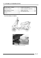
. GENERAL INFORMATION 1ENGINE SERIAL NUMBER ...................1- 1 LUBRICATION POINTS......................1-13 SPECIFICATIONS .................................1- 2 CABLE & HARNESS ROUTING.........1-15 SERVICE PRECAUTIONS.....................1- 3 WIRING DIAGRAM...............................1-20 TORQUE VALUES..................................1-11 TROUBLESHOOTING.........................1-21 TOOLS.....................................................
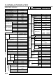
1. GENERAL INFORMATION SPECIFICATIONS Cooling Type Air cleaner type & No Paper element, wet Fuel capacity 7.8 liters Type VE45 Piston dia. (mm) 24 Venturi 22.1 equivalent dia.(mm) Throttle type Butterfly type Type CDI Ignition timing 13±3°BTDC/1700rp m point Contact breaker Non-contact type NGK ND C6HSA U20FS-U Spark plug C7HSA U22FS-U C8HSA U24FS-U Spark plug gap 0.6_ 0.
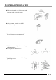
1. GENERAL INFORMATION SERVICE PRECAUTIONS n Make sure to install new gaskets, O-rings, circlips, cotter pins, etc. when reassembling. n When tightening bolts or nuts, begin with larger-diameter to smaller ones at several times, and tighten to the specified torque diagonally. n Use genuine parts and lubricants. n When servicing the motorcycle, be sure to use special tools for removal and installation. n After disassembly, clean removed parts. Lubricate sliding surfaces with engine oil before reassembly.
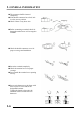
1. GENERAL INFORMATION n Apply or add designated greases and lubricants to the specified lubrication points. n After reassembly, check all parts for proper tightening and operation. n When two persons work together, pay attention to the mutual working safety. n Disconnect the battery negative (-) terminal before operation. n When using a spanner or other tools, make sure not to damage the motorcycle surface.
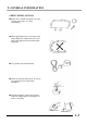
1. GENERAL INFORMATION n If the fuse is burned out, find the cause and repair it. Replace it with a new one according to the specified capacity. Confirm Capacity n After operation, terminal caps shall be installed securely. n When taking out the connector, the lock on the connector shall be released before operation. n Hold the connector body when connecting or disconnecting it. n Do not pull the connector wire. n Check if any connector terminal is bending, protruding or loose.
1. GENERAL INFORMATION n The connector shall be inserted completely. n If the double connector has a lock, lock it at the correct position. n Check if there is any loose wire. n Before connecting a terminal, check for damaged terminal cover or loose negative terminal. n Check the double connector cover for proper coverage and installation. n Insert the terminal completely. n Check the terminal cover for proper coverage. n Do not make the terminal cover opening face up.
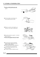
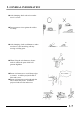
1. GENERAL INFORMATION n After clamping, check each wire to make sure it is secure. n Do not squeeze wires against the weld or its clamp. n After clamping, check each harness to make sure that it is not interfering with any moving or sliding parts. n When fixing the wire harnesses, do not make it contact the parts which will generate high heat. n Route wire harnesses to avoid sharp edges or corners. Avoid the projected ends of bolts and screws.
1. GENERAL INFORMATION n Route harnesses so they are neither pulled tight nor have excessive slack. Do not pull too tight! n Protect wires and harnesses with electrical tape or tube if they contact a sharp edge or corner. n When rubber protecting cover is used to protect the wire harnesses, it shall be installed securely. n Do not break the sheath of wire. n If a wire or harness is with a broken sheath, repair by wrapping it with protective tape or replace it.
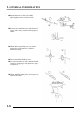
1. GENERAL INFORMATION n After routing, check that the wire harnesses are not twisted or kinked. n Wire harnesses routed along with handlebar should not be pulled tight, have excessive slack or interfere with adjacent or surrounding parts in all steering positions. n When a testing device is used, make sure to understand the operating methods thoroughly and operate according to the operating instructions.
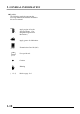
1. GENERAL INFORMATION n Symbols: The following symbols represent the servicing methods and cautions included in this service manual. Engine Oil Grease Gear Oil Special * : Apply engine oil to the specified points. (Use designated engine oil for lubrication.) : Apply grease for lubrication. : Transmission Gear Oil (90#) : Use special tool. : Caution : Warning (!12-3) 1-10 : Refer to page 12-3.
1. GENERAL INFORMATION TORQUE VALUES STANDARD TORQUE VALUES Item 5mm bolt, nut 6mm bolt, nut 8mm bolt, nut 10mm bolt, nut 12mm bolt, nut Torque (kg-m) 0.5 1.0 2.2 3.5 5.5 Item 5mm screw 6mm screw, SH bolt 6mm flange bolt, nut 8mm flange bolt, nut 10mm flange bolt, nut Torque (kg-m) 0.4 0.9 1.2 2.7 4.0 Torque specifications listed below are for important fasteners.
1.
1.
1. GENERAL INFORMATION FRAME The following is the lubrication points for the frame. Use general purpose grease for parts not listed. Apply clean engine oil or grease to cables and movable parts not specified. This will avoid abnormal noise and rise the durability of the motorcycle.
1.
1.
1.
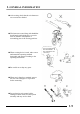
1. GENERAL INFORMATION Vacuum Tee Crankcase Breather Tube Ignition Coil Fuel Valve Vacuum Tube Throttle Cable Auto Bystarter Wire Fuel Tube A.C.
1.
1.
1.
1.
1.
1.
1. GENERAL INFORMATION POOR CHARGING (BATTERY OVER DISCHARGING OR OVERCHARGING) Undercharging Inspection/Adjustment Symptom Probable Cause Start engine and test limit voltage of battery terminals Normal voltage Voltage does not increase Dead battery Faulty battery Measure resistance between AC generator coil terminals Connect battery (+) wire to regulator/rectifier coupler red wire and battery (-) wire to engine ground and test voltage Faulty A.C.
1.