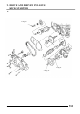
9. DRIVE AND DRIVEN PULLEYS/ KICK STARTER 9 5.5kg-m 5.5kg-m 5.
9. DRIVE AND DRIVEN PULLEYS/ KICK STARTER SERVICE INFORMATION ......................9-1 DRIVE PULLEY......................................9- 3 TROUBLESHOOTING.............................9-1 CLUTCH/DRIVEN PULLEY..................9- 8 LEFT CRANKCASE COVER ...................9-2 KICK STARTER.....................................9-14 SERVICE INFORMATION GENERAL INSTRUCTIONS • The drive pulley, clutch and driven pulley can be serviced with the engine installed.
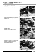
9. DRIVE AND DRIVEN PULLEYS/ KICK STARTER LEFT CRANKCASE COVER Air Tube Band REMOVAL Loosen the drive belt air tube band screw. Cable Clamp Screw Left Crankcase Cover Remove the left crankcase cover bolts and left crankcase cover. Remove the seal rubber and dowel pins. Bolts Dowel Pins INSTALLATION Install the dowel pins and seal rubber. Seal Rubber Install the left crankcase cover and tighten the left crankcase cover bolts. Install the cable clamp to the specified location and tighten the bolt.
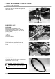
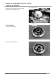
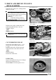
9. DRIVE AND DRIVEN PULLEYS/ KICK STARTER Intake Cover Install the drive belt air tube and tighten the tube band screw. Tube Band Screw Starting Ratchet Drive Pulley Face DRIVE PULLEY REMOVAL Remove the left crankcase cover. Hold the drive pulley using an universal holder and remove the drive face nut and starting ratchet. Remove the drive pulley face. Special Universal Holder Universal Holder Hold the clutch outer with the universal holder and remove the clutch outer nut.
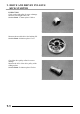
9. DRIVE AND DRIVEN PULLEYS/ KICK STARTER Remove the movable drive face assembly. Remove the drive pulley collar. Drive Pulley Collar Movable Drive Face Assembly DISASSEMBLY Remove the ramp plate. Ramp Plate Remove the weight rollers.
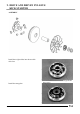
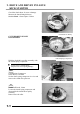
9. DRIVE AND DRIVEN PULLEYS/ KICK STARTER INSPECTION Check each weight roller for wear or damage. Measure each weight roller O.D. Service Limit: 17.4mm replace if below Measure the movable drive face bushing I.D. Service Limit: 24.06mm replace if over Check the drive pulley collar for wear or damage. Measure the O.D. of the drive pulley collar sliding surface. Service Limit: 23.
9. DRIVE AND DRIVEN PULLEYS/ KICK STARTER ASSEMBLY Install the weight rollers into the movable drive face. Install the ramp plate.
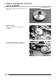
9. DRIVE AND DRIVEN PULLEYS/ KICK STARTER Drive Pulley Collar Insert the drive pulley collar into the movable drive face. INSTALLATION Install the movable drive face onto the crankshaft. Movable Drive Face Assembly Drive Pulley Collar Driven Pulley Lay the drive belt on the driven pulley. Set the drive belt on the drive pulley collar.
. DRIVE AND DRIVEN PULLEYS/ KICK STARTER Install the drive pulley face, starting ratchet and drive face nut. Drive Pulley Face *• When installing the drive pulley face, compress it to let the drive belt move downward to the lowest position so that the drive pulley can be tightened. • Install the starting ratchet by aligning the starting ratchet teeth with the crankshaft teeth. Hold the drive pulley with the universal holder and tighten the drive face nut. Torque: 5.
9. DRIVE AND DRIVEN PULLEYS/ KICK STARTER Check the clutch shoes for wear or damage. Measure the clutch lining thickness. Service Limit: 1.5mm replace if below Clutch/Driven Pulley CLUTCH/DRIVEN PULLEY DISASSEMBLY Hold the clutch/driven pulley assembly with the clutch spring compressor. Clutch Spring Compressor * Be sure to use a clutch spring compressor to avoid spring damage.
9. DRIVE AND DRIVEN PULLEYS/ KICK STARTER Pull out the guide roller pins and guide rollers. Remove the movable driven face from the driven face. Guide Roller Pin Guide Roller Movable Driven Face Remove the oil seal from the movable driven face. O-ring Oil Seal INSPECTION Measure the driven face spring free length. Service Limit: 163.7mm replace if below Check the driven face for wear or damage. Measure the driven face O.D. Service Limit: 33.
9. DRIVE AND DRIVEN PULLEYS/ KICK STARTER Check the movable driven face for wear or damage. Measure the movable driven face I.D. Service Limit: 34.06mm replace if over DRIVEN PULLEY FACE BEARING REPLACEMENT Drive the inner needle bearing out of the driven pulley face. * Discard the removed bearing and replace with a new one. Inner Bearing Remove the snap ring and drive the outer bearing out of the driven face. * Discard the removed bearing and replace with a new one. Apply grease to the outer bearing.
9. DRIVE AND DRIVEN PULLEYS/ KICK STARTER Press a new needle bearing into the driven face. Special Bearing Driver Pilot, 20mm Circlip CLUTCH DISASSEMBLY Remove the circlips and retainer plate to disassemble the clutch. * Keep grease off the clutch linings.
9. DRIVE AND DRIVEN PULLEYS/ KICK STARTER CLUTCH ASS EMBLY Install the damper rubbers on the drive plate pins. Install the clutch weights/shoes and clutch springs onto the drive plate. Install the retainer plate and secure with the circlips. CLUTCH/DRIVEN PULLEY AS SEMBLY Clean the driven pulley faces and remove any grease from them. Install the oil seal onto the moveable driven face. Apply grease to the O-rings and install them onto the moveable driven face.
9. DRIVE AND DRIVEN PULLEYS/ KICK STARTER Install the movable driven face onto the driven face. Apply grease to the guide rollers and guide roller pins and then install them into the holes of the driven face. Guide Roller Driven Face Guide Roller Pin Movable Driven Face Install the seal collar. Remove any excessive grease. * Be sure to clean the driven face off any grease. Set the driven pulley assembly, driven face spring and clutch assembly onto the clutch spring compressor.
9. DRIVE AND DRIVEN PULLEYS/ KICK STARTER Clutch Outer Install the clutch outer. Hold the clutch outer with the universal holder. Install and tighten the clutch outer nut. Torque: 5.5kg-m Special Universal Holder Install the drive belt. (!9-7) Install the left crankcase cover. (!9-2) Universal Holder KICK STARTER REMOVAL Remove the left crankcase cover. (!9-2) Remove the seal rubber and dowel pins. Remove the kick lever. Remove the circlip and washer from the kick starter spindle.
9. DRIVE AND DRIVEN PULLEYS/ KICK STARTER Kick Starter Spindle Remove the kick starter spindle and return spring from the left crankcase cover. Remove the kick starter spindle bushing. Return Spring Spindle INSPECTION Inspect the kick starter spindle and gear for wear or damage. Inspect the return spring for weakness or damage. Inspect the kick starter spindle bushings for wear or damage. Inspect the starter driven gear for wear or damage. Inspect the friction spring for wear or damage.
9. DRIVE AND DRIVEN PULLEYS/ KICK STARTER INSTALLATION Install the kick starter spindle bushings and return spring onto the left crankcase cover. * When installing the return spring, use a screw driver to press the inward and outward return spring hooks into their original positions respectively. Kick Starter Spindle Install the starter driven gear and friction spring as the figure shown. Install the kick lever. Install the left crankcase cover and tighten the cover bolts diagonally.