B/W-MULTIFUNCTIONAL SYSTEM FOR PAPERSIZE UP TO A3 FS-6025MFP/ FS-6030MFP
M d l name: TPM-6030MFP Module TPM 6030MFP KYOCERA ACADEMY Author: U. Kunter Creation: 03/11 Version: 1.0 Note: All the contents of this document have been carefully researched. However, we cannot assume liability for the information provided being accurate, complete and up to date.
Note for students This training manual contains information, topics for discussion, exercises concerning your course, and is organized into individual “lessons”. The aim of organizing it in this way is to gain practical knowledge by following specific, carefully structured (learning) steps as presented in our Learning Units (LU ). In order to make the training material simpler and clearer, we have marked the most important learning points with symbols. This symbol indicates Learning Objectives.
LE 01 Overview At a look DF-470 500 Sheet Finisher AK-470 Bridge unit FS-6030MFP FS-6025MFP FS-6020/ FS 6020/ B (without Document Processor) PF-470 500 sheet x 1 cassette paper feeder + cabinet PF-471 500 sheet x 2 Cassette paper feeder FAX System (U) IB-50 IB 50 Gigabit Ethernet USB Keyboard Card Reader Holder UG-33 Thin Print Activation kit These Options will be activated by the registration on the Kyocera Mita Homepage Card Authentication Kit(B)
LE 01 Overview Options in detail DP Original size: A5 –A3 Paper weight: Simplex: 45 – 160 g/m² Duplex: 50 – 120 g/m² max.
LE 01 Overview Options in detail Fax System (U) ITU-T Super G3 Modem: max. 33,6 Kbit/s Data transferrate max. 3 Sekunden (with JBIG) Scan resolution: normal, fine, superfine, ultrafine Operating sytem: Networkfax: Windows 2000/XP/Vista/7/Server 2003/Server 2008 Original size: up to A3 Compressions approach: JBIG, MMR, MR, MH Fax properties: Fax, Networkfax, Duplex-receipt/-sending, encrypted receipt/-sending, fax polling.
LE 01 Overviewt Touch panel The touch panel is a new LCD panel with the simple handling in Kyocera typical style. A lot of functions are controlled by big icons, which makes the handling easier easier.
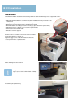
LE 02 Installation Installation The initial installation should be carried out by technical staff. The following reasons support this advice: • Although initial installation is documented ("Quick Installation Guide"), instructions are seldom read. • Transport safety devices are sometimes not recognized or removed. • Damage from transportation can be identified beforehand. • Brief introduction according to customer needs (e (e.g. g tips about toner replacement).
LE 02 Installation I t ll ti (continuation) Installation The scanner locking is needed for the transport of the machine. If you didn’t unlock, the display shows call service (C3100). In this case, switch off the machine unlock the lever and switch on the machine. By every transport you have to use this securing device device. In maintenance mode U002 the scanner move’s to the transport position and you can lock the scanner. The lever is also protected.
LE 03 Construction 1. Cassette 2. Cassette paper feed section 3 MP tray paper feed section 3. 4. Conveying section 5. Transfer/Separation section 6. Charger roller unit 7. Drum unit 8. Developer unit 9. Toner container 10. Fuser unit 11. Eject section 12. Duplex/conveyning section 13. Image scanner unit (ISU) 14. Laser scanner unit (LSU) 15.
LE 03 Construction Paper p feeder By inserting the cassette the liftmotor (LM) starts. It stops by swichting the LIFTFULL sensor. The automatic paper size detection is controlled by sensor PWSW (width) and PLSW1 – 3 (length). Paper cassette level The paper level in the cassette is detected by 2 sensor‘s on the rear of the machine. (PAPEMP1 and 2) Note For easier replacement of the paper feed unit, the LIFTFULL sensor is installed in the bottom plate of the frame.
LE 03 Construction Paper cassette The paper cassette automatically detect’s the paper size by PWSW (width) and PLSW (lenght) switches. To prevent paper jam by overload of the cassette, the lift plate goes down by slide in the cassette. Note In Systemmenu/Counter Æ Cassette-/Universalsettings it‘s possible to select metric or inch for each cassette. So mixed use is possible.
LE 03 Construction Paper p feed unit 1. Main Motor 2. Paper feed clutch 3. Regist clutch 4. Duplex clutch 5 5.
LE 03 Construction Paper p feed unit The registration roller has a big diameter to prevent paper curl. Feed from the cassette’s The Paper feed drive is started approximately 25ms prior to the secondary feed for registration of the leading edge of the paper.
LE 03 Construction Duplex unit The Job Separator is used to turn around the paper for duplex printing printing. Therefore it’s it s better when the tray is empty.
LE 03 Construction D Drum unit it The main parts of the drum unit are: • a-Si drum • Charge roller • Cleaning g blade and cleaning g roller • LED-bracket to erase • Sweep roller for waste toner • DK Relay PWB The drum surface p potential is 270V ((+/-20V)) The waste toner bottle is controlled by a LED (WTL) - Sensor (WTS) combination. The life time of the drum is specified to 300.000 pages. 1. Drum 2. Charger roller 3. Charger cleaning roller 4. Charger case 5. Cleaning g blade 6. Cleaning roller 7.
LE 03 Construction Developing unit Mono component system 300.000 pages DC Voltage Vdc 160 V AC Voltage Vpp 1.80 kV No Toner sensor available. As soon as the Main motor moves, toner is transported from the toner catridge into the developer unit 1. Developing roller 2. Developing screw A 3. Developing screw B 4. Developing blade 5. Magnet blade 6. Developer case 7. Upper developer cover 8.
LE 03 Construction Transfer and Separation The transfer of the toner from the drum to the paper happens by the transfer unit. The separation is done by separation needles and a bias voltage, as also by the drum separator which pick up the paper mechanically from the drum. Contact springs for transfer- and separation voltage..
LE 03 Construction Fuser unit The Fuser unit is only available as one unit. The most important specifications are: 1 contact Thermostat on the edge of the heat roller. 2 Thermistor’s for controlling overheat . 2 Fuser heater Drive start timing: 135°C Ready : 150°C Print:165 Print:165° The disassembling of the fuser unit is complicated. A reset in Maintenance Mode isn’t necessary after C6XXX error code. Reset is possible by power off/on the system.
LE 03 Construction Eject unit The Eject unit has 2 trays. The main tray is the inner tray. The secondary tray is the Job Separator. Th These ttrays are controlled t ll d b by EPS sensor (Eject_Full_Upper) and PFS sensor (Eject_Full_Lower), also by JEPS (Job eject papersensor). The capacity of the Job Separator is normally 50 sheets 80g/m², but it is possible to store more then 100 sheets sheets.
LE 03 Construction Laser Scanner Unit Despite the speed of more than 39600 rpm the LSU is quiet, because the polygon mirror is only 30mm. The motor of the polygon mirror stops immediately at the end of printing.
LE 03 Construction Scanner unit The scanner has something new. For example the new LED bracket with 28 LED‘s. For an equal light spread over the LED bracket is a light guide plate. The advantage of LED is the lower energy consumption and the lower heat development. So it‘s possible to seal the scanner unit and thereby the scan system is free of maintenance.
LE 03 Construction Scanner unit The Image Scanner Unit is fixed with 4 screws. After replacing the unit the number on the lens must align with the scale. After replacing the LED bracket or ISU it‘s necessary to make a scanner calibration with test chart 7505000005.
LE 03 Construction Miscellaneous Behind the front inner cover you will find the Humidity Sensor (1), Interlockswitch (2) and DK connection PWB (3) 1. Scanner Motor 2. Drive unit with Main Motor 3. Engine PWB 4. Main PWB 5. Relay PWB 6.
LE 03 Construction Miscellaneous Below the Inner Tray and the fan duct you will find more components. 1. 2. 3 3. 4. 5. LVU sub PWB AC cut PWB (Relay PWB) LVU main PWB LSU High voltage PWB Since February 2011 the LVU main PWB is modified so that the AC cut PWB (Relay PWB) is not longer needed.
LE 03 Construction PWB s PWB’s 1. Main PWB (MPWB) 2. Engine PWB (EPWB) 3. High Voltage PWB (HVPWB) 4. Power source PWB (PSPWB) 5. Power source PWB – sub (PSBWB-S) 6. Operation panel PWB main (OPPWB-M) 7. Operation panel PWB left (OPPWB-L) 8. Operation panel PWB right (OPPWB-R) 9. LCD-PWB (LCDPWB) 10. LCD relay PWB (LCDRPWB) 11. CCD PWB (CCDPWB) 12. APC PWB (APCPWB) 13. BD PWB (BDPWB) 14. DRUM PWB (DRPWB) 15. Drum relay PWB (DRRPWB) 16. Developing PWB (DEVPWB) 17 Developing relay PWB (DEVRPWB) 17. 18.
LE 03 Construction Switch and sensor 1. Home position sensor (HPS) 2. Original detection switch (ODSW) 3. Original size sensor (OSS) 4. Front cover switch (FCSW) 5. Right cover switch (RCSW) 6. Feed sensor (FS) 7. MP paper sensor (MPPS) 8. Registration sensor (RS) 9. Duplex sensor (DUS) 10. Eject sensor (ES) 11. Paper full sensor (PFS) 12. Job paper full sensor (JPFS) 13. Paper sensor 1 (PS1) 14 P 14. Paper sensor 2 (PS2) 15. Lift sensor (LS) 16. Paper size width switch (PWSW) 17.
LE 04 Maintenance Maintenance Kits For maintenance there is no tool kit necessary. After assembling the units you have to reset the maintenance call. Therefore select Service Menu Æ Adjustment/ Maintenance Æ Service Adjustment. The scanner is free of maintenance, so you only have to clean the contact glas and the slit glass. Maintenance interval: 300.
LE 04 Maintenance Cover disassembling Most of the cover parts are fixed without screws. It’s important to look at the hook points and to know the proper sequence for disassembling. We start with the Rear cover. Firstly remove the DP-connector. Then remove 6 screws (see picture at the right) and pull the rear cover upwards and release 3 hooks. And now to the Left lower cover. Firstly remove the upper cassette and open the front cover. Remove 2 screws. Release 3 hooks (A).
LE 04 Maintenance Cover disassembling To disassemble the front upper cover, remove the cassette, open the front cover and d open allll covers on the th right i ht side. id Release 2 hooks of the front upper cover and tilt the cover forward. Now we can disassemble the inner tray. To remove the tray left cover release the hook by using a flat screwdriver. Remove the eject upper cover while supporting the rear tray cover.
LE 04 Maintenance Cover disassembling Remove the inner rear tray cover by pulling it out on the left side first. Remove one screw and the connector. And then remove the power source fan duct.
LE 04 Maintenance Firmware upgrade The Firmware includes several different files and the data size is approximately 105MB. Please use always the complete Firmware file for the upgrade upgrade. If you store also the SKIP File Data on the USB memory stick, you only upgrade the parts of firmware which are different. This may be much faster. If you want to upgrade the whole firmware you have to delete the skip file first.
LE 04 Maintenance U 425 automatically calibration of the scanner U-425, After repairing or replacement of the CCD unit, scanner, New calibration chart 7505000005 scanner-LED bracket or control PWB. LAB value with Barcode on the test chart. • calibration chart (P/N: 7505000005). The calibration start with input of the LAB values. These LAB values are notified on the chart. chart After entering the values it’s absolutely necessary to do the calibration with the supplied chart.
LE 04 Maintenance U-425,, automatically y calibration of the scanner (Follow up) 1. Place the calibration chart on the contact glass. 2. Close the document processor carefully so that the chart doesn’t move. 3. Activate the maintenance mode. 4. U-411 and select „01 Table“ . 5. Quit with OK. The scanner starts its processes. Leading edge After 1 minute „OK“ should displayed. If the calibration is not successful the display shows „NG“. Control the position of the calibration chart and try it once more.
LE 04 Maintenance System settings Activity Entry in the service settings (Adjustment/Maintenance). Recommendation • If the copier or print quality is bad. • If you need a detail report of the technical settings (for technician). • For settings of the fax connectivity. • For special settings (by moving location or replacing units). Tip • Detailed information in the operation guide (^ÇàìëíãÉåíLj~áåíÉå~åÅÉ). • Some settings are only available for the administrator.
LE 04 Maintenance System menu Auto Color Correction This setting allows you to adjust the detection level used by the machine to determine whether the original is color or black and white during Auto Color Mode. Setting a lower value will result in more originals being identified as color, while a larger value will tend to increase the number of originals being identified as black and white.
LE 04 Maintenance Maintenance mode Activity Enter the maintenance mode. Recommendation • For setting the U-Parameter • To print special reports (Eventlog) • To print test charts for adjustments • To adjust and calibrate the machine Requirement • Knowledge of how to use the maintenance mode. • Knowledge about the functions of the U-Parameter.
LE 04 Maintenance Maintenance mode Section Item No.
LE 04 Maintenance Maintenance mode Section Item No.
LE 04 Maintenance Maintenance mode Section Mode setting Item No. Content of maintenance item Default setting* U326 Setting the black line cleaning indication ON U332 Setting the size conversion factor 1.0 U341 Specific paper feed location setting for printing function - U343 Switching between duplex/simplex copy mode OFF U345 Setting the value for maintenance due indication 0 U402 Adjusting margins of image printing 3.0/2.5/3.0/5.
LE 04 Maintenance Image adjustment procedure Step Adjustment Image 1 Print width (Main scan) B=250mm+/-1,0mm 2 Print length 3 A=350mm+/-1,4mm Centering the image position 20mm +/-1,0mm f from the th page edge d Setting maintenance mode Note/ remark Adjustment of the poligon motor speed. U53 Adjust motor speed POLY GONMOTOR Test printout inU53. Press system menu key. Adjustment of the main motor speed. U53 Adjust motor speed MAINMOTOR Test printout in U34, system menu key.
LE 04 Maintenance Image processing Step Adjustment Image Setting maintenance mode 9 Adjustment of parallelism of the Document processor p Adjustment of the DP hinge 10 Copy size scanner in main scanning direction U65 Adjust scanner motor speed Y SCAN ZOOM U70Adjust DP motor speed Y SCAN ZOOM Copy A3 test page on the original glass and via DP.
LE 04 Maintenance Paper jam detection Paper jam The code of the paper jam has 4 digits. So the description of the paper jam position is more exactly. Example: Jam 0501 05 – paper feed Æ 0 – no paper feed Æ 1 – cassette 1 Paper doesn’t arrive the registration sensor.
LE 04 Maintenance User Login Administration A new feature of the configuration menu is My Panel. If the User Login Administration is enabled, maximum 100 accounts can be configured. If Simple Login enabled, 20 user’s have their own simple login to get to their personal screen. If the user has an accounting name, it’s possible to connect them with the local authentication. If you need to get past the Simple Login you have to use the menu button to enter the below login menu.
LE 05 Command Center C t t Contents: • Access • Design • Helpful hints • Safety concept • Passwords • Blocking the Operation Panel • Blocking interfaces • IP filter • Local authentication • Network authentication At the end of the chapter you will be able to... • integrate the device in the network. • have an informed dialog with the administrator. • protect the device from unauthorized network access (flexible securityconcept). • set up different network scan modes.
LE 05 Command Center Access to the Command Center Access to the Command Center is available via a web browser (e.g. internet Explorer, Mozilla Firefox etc.). Enter the IP address or the host name of the printer or multifunction device in the browser's address bar. Example: http://192.168.100.25 htt //192 168 100 25 or http://KM4C3174 If the Command Center is called up, access is limited for security reasons. Apart from setting the Command Center's language, no other settings can be made.
LE 05 Command Center Design of the Command Center The Command Center is divided into the following areas: 1. Main Menu Access to the main functions of the Command Center. If no login for the Command Center takes place, the “Start” menu appears. 2. Submenu The contents depend on which item was chosen in the main menu. If there is a ► after the menu item, more submenus are located there. By moving the mouse over it, these become visible. Each submenu is colored differently for better differentiation.
LE 05 Comman Center LE 05 Command Center Style of presentation in this manual Each function of the Command Center is described in the following pages. The presentation of nested menu structures and the corresponding screenshots have been modified here due to space restrictions. Example: Danach eine Schraube des Duct Fan am linken Rahmen lösen und die Einheit entfernen. The presentation of the Command Center is structured as follows: 1 Submenu The submenu is subordinate to the main menu.
LE Command 05 Command Center LE 05 Center Helpful hints Entries All entries in the Command Center have to be confirmed using the “Send” button, only then are the data sent to the device. Some entries take a little time so be sure to keep an eye on the progress bar bar. Password • The access password (admin00) should be changed as soon as possible so that there is optimal protection • In principle, it is possible NOT to define ANY password.
LE 05 Command Center LE 05 Command Center Safety Concept Requirements Measure The device's system settings have to be protected. The system settings are protected by a standard account (DeviceAdmin) (FS-6025: 2500 / 2500 and FS-6030: 3000 / 3000 This standard account should be changed as required to ensure long-term security. It is also practical to set up an additional account to ensure access if the "official“ password is lost or unknown (should be arranged with the customer).
LE 05 Command Center LE 05 Command Center Device safety Measure The start page is the starting point for various settings to increase the network's operational dependability. Recommendations Part of a security concept. Pre-conditions Administrative access to the Command Center. Notes On this start page, the relevant areas are briefly explained. By clicking on the underlined terms the desired setup area can be reached. Some settings require, where necessary, a network administrator's presence.
LE 05 Command Center Change password Action Password change for accessing the Command Center. Recommendations • Access to the Command Center should generally be protected. • The password should be changed at regular intervals. • Part of a security concept. Pre-conditions Administrative access to the Command Center. Notes If the password has been forgotten, the only option is to reset to the factory settings. All network and authentication settings are thereby lost.
LE 05 Command Center Blocking the operation panel Action Blocking the system menu of the device. Recommendations • If arbitrary system settings and system changes are to be prevented. • If specifically qualified personnel is responsible for maintaining the device. • Part of a security concept. Pre-conditions Administrative access to the Command Center. Notes • In the locked status, access to system settings is possible from the operation panel with the help of the administrator account.
LE 05 Command Center Blocking the Interfaces Action Targeted blocking of the device's interfaces. Recommendations • If unauthorized use of the device is to be prevented (e.g. to print holiday photos). • If arbitrary firmware updates are to be prevented (e.g. USB host). • Part of a security concept. Pre-conditions Administrative access to the Command Center. Notes • After setup, the device has to be switched off briefly so that the status can be activated.
LE 05 Command Center Network safety Measure Targeted activation of transfer protocols. Recommendations • Only those protocols should be activated that are required for communicating with the device. • Part P t off a security it concept. t Pre-conditions Administrative access to the Command Center.
LE 05 Command Center IP-Filter IP Filter (v4 and v6) Measure Setup of exclusive communication addresses Recommendations • Only very specific computers may connect to the device. • Only a very specific address range may communicate with the device within the network. t k • When communicating, the device may only use specific protocols. Pre-conditions Administrative access to the Command Center. Notes • This page is linked to the menu "Basic/device security".
LE 05 Command Center Authentication models No authentication Admin / Admin admin00 • Administrative access to the Command Center with ONE password *). • Generally open access*). • No personal access (only password). • Access limitations possible via cost center mode. • Unprotected access possible. •For security reasons, administrative access to the Command Center in the factory default settings is protected.
LE 05 Command Center Authentication models Local authentication max. 200 accounts • General access barrier to the Command Center and device. • Personalized access (ID and password) for Command Center and device. • Access restrictions via user status (administrator/ user) possible. • Cost Centers can be linked to the registered account. Up to 100 user accounts can be set up via the Command Center and via the operation panel.
LE 05 Command Center Authentication models Network authentication Server ADS User accounts in ADS max. 50 groups • General access barrier to the Command Center and device. • Personalized access (ID and password) for Command Center and device. • Access restrictions via user status (administrator / user) possible. • By using group authorization, certain rights can be assigned to the account for the use of the device. ADS (Active Directory Services) has to be available.
LE 05 Command Center User login (user authentication) Action Creating personalized accounts (local). Recommendations • Only certain persons may administer the cost centers. • Only certain persons may apply administrative settings to the device. • Only certain persons are allowed to have administrative access to the Command Center. Center • Only certain persons may use the device. • Certain persons are subject to limitations (copy, scan, print etc.
LE 05 Command Center Authentication Action Specifying the authentication Recommendations When generally a person-specific authentication is wanted for the device. Pre-conditions • Administrative access to the Command Center • Local user accounts (see page 94) or network accounts via AD S (Active Di t Directory S Services) i ) mustt be b available. il bl Notes As very detailed knowledge of networks is required for this, it is recommended that the network administrator is present for the setup.
LE 05 Command Center Authentication administrator status Authentication, Full access to the Command Center and to the device's system menu.
LE 05 Command Center Authentication user status Authentication, Limited access to the Command Center and to the device's system menu.
LE 05 Command Center Group authorization (for network authentification) Action Mapping a user profile for network authentication. Recommendations When different personalized access rights to the device are desired. Pre-conditions • Administrative access to the Command Center. • Network access via AD S (Active Directory Services) has to be available. Notes As very detailed knowledge of networks is required for this, it is recommended that the network administrator is present for the setup.
LE 05 Command Center Scan via network network, preparations The following scan modes are available via the network: • Scan to email • Scan to SMB • Scan to FTP For these scan modes, basic settings can be specified.
LE 05 Command Center S Scanning, i Scan-to-Email S t E il Action Scan to e-mail accounts.
LE 05 Command Center S Scanning, i Scan-to-Email S t E il (continued) ( ti d) 1 2 3 4 1. If the preset size limit is exceeded, the scan aborts with an error message and the file is not transferred. 2. Entering the sender's address is mandatory (!), otherwise Scan-to-Email cannot be carried out. For practical purposes, the sender's address should be an active address so that, for example, there is a reply to the scan email. 3.
LE 05 Command Center S Scanning, i Scan-to-FTP S t FTP Action Scan to FTP recources Recommendations If there is a requirement for sending scanned objects via FTP transfer Pre-conditions • Administrative access to the Command Center. • FTP resource (FTP server) can be accessed via the network. Notes Though address entries can be made via the operation panel, it is recommended for this device that the FTP target addresses are stored.
LE 05 Command Center S Scanning, i Scan-to-SMB S t SMB Action Scan to Windows Services (e.g. in folder) Recommendations If there is a requirement for sending scanned objects To Windows Services Pre-conditions • Administrative access to the Command Center. • Services can be accessed via the network. Notes Though SMB address entries can be made via the operation panel, it is recommended that target addresses for this device are stored.
LE 05 Command Center S Scanning, i Scan-to-SMB S t SMB Action Scan to Windows Services (e.g. in folder) Recommendations If there is a requirement for sending scanned objects To Windows Services Pre-conditions • Administrative access to the Command Center. • Services can be accessed via the network. Notes Though SMB address entries can be made via the operation panel, it is recommended that target addresses for this device are stored.
LE 05 Command Center S Scanning, i Send S d and d forward f d Action Forward a sent file to a specified destination Recommendations If there is a requirement to control sent documents. Pre-conditions • Administrative access to the Command Center. • Customer setup is depending on receiver for E-mail, FTP and SMB.
LE 05 Command Center Add Address book, b k local l l Action Setting up a local address book for selection of scan and fax destinations. Recommendations If scanning and faxing are always to be used for the same destinations. Pre-conditions Administrative access to the Command Center. Notes • Address entries are stored in the device in question. • Via U-917 these entries can be stored on a USB device and transferred to another FS-6025/6030MFP or FS-C8020/8025MFP • Via the KM NetViewer (5.
LE 05 Command Center S di service Sending i lists li t By means of the following entry in the browser's address bar: http:///svcmntrpt an HT ML page is called up that can be used to send specific service reports via e-mail. 1 2 3 4 5 6 7 1 Mail address to which the desired reports p can be sent ( as attachment). ) 2 Automated terms (strings) that appear in the subject line. 3 Option for the relevant list(s). 4 File format of the list (HT ML or TXT). 5 Activation of the body text.
LE 05 Command Center Add Address book, b k local l l Action Reset / restart Recommendations • With network settings via the Command Center • Where there are changes to the status of interfaces via the Command Center • When a reset to the factory settings is desired Pre-conditions Administrative access to the Command Center. Notes When selecting, different functionalities have to be taken into account 1 2 3 1 Restart Is identical to switching the device off and on.
Blank Page
If yoU hAve ANy qUestIoNs... coNtAct Us! Do you require information about the training or one of our detailed information brochures about individual training programs? Contact us at: kyocera_academy@kyoceramita-europe.com Or visit our website: http://www.kyocera-academy.de Kyocera Academy Otto-Hahn-Str.