Please read the instruction handbook before using the printer. Keep it close to the printer for easy reference. INSTRUCTION HANDBOOK Laser Printer The DP-3600 in this photograph is equipped with two optional paper feeders (ST1000) and an optional document finisher (F-8118).
Introduction Please read the instruction handbook before using the printer. Keep it close to the printer for easy reference. The sections of this handbook and parts of the printer marked with symbols are safety warnings meant to protect the user, other individuals and surrounding objects, and ensure correct and safe usage of the printer. The symbols and their meanings are indicated below. The symbol indicates that the related section includes information on prohibited actions.
Introduction Caution NO LIABILITY IS ASSUMED FOR ANY DAMAGE CAUSED BY IMPROPER INSTALLATION. Notice on Software_____________________________________________________________________________________ SOFTWARE USED WITH THIS PRINTER MUST SUPPORT THE PRINTER’S NATIVE MODE OR ONE OF ITS EMULATION MODES. The printer is factory set to emulate the HP LJ 5M/5Si. The emulation mode can be changed by following the procedures described in Chapter 2.
Introduction IBM PROGRAM LICENSE AGREEMENT ____________________________________________________________________ THE DEVICE YOU HAVE PURCHASED CONTAINS ONE OR MORE SOFTWARE PROGRAMS (“PROGRAMS”) WHICH BELONG TO INTERNATIONAL BUSINESS MACHINES CORPORATION (“IBM”). THIS DOCUMENT DEFINES THE TERMS AND CONDITIONS UNDER WHICH THE SOFTWARE IS BEING LICENSED TO YOU BY IBM.
Introduction 3. Limitation of Remedies IBM’s entire liability under this license is the following; 1) For any claim (including fundamental breach), in any form, related in any way to this license, IBM’s liability will be for actual damages only and will be limited to the greater of: a) the equivalent of U.S.
Introduction Typeface Trademark Acknowledgement____________________________________________________________________ All resident fonts in this printer are licensed from Bitstream Inc., Cambridge, Massachusetts, U.S.A. Dutch801, Swiss742, Incised901, ZapfCalligraphic801, ZapfHumanist601, OriginalGaramond, and Chianti are trademarks of Bitstream Inc. Century Schoolbook, Stymie, and Cooper-Black are trademarks of Kingsley-ATF Type Corporation.
Introduction FCC statement This device complies with Part 15 of the FCC Rules. Operation is subject to the following two conditions: (1) This device may not cause harmful interference, and (2) this device must accept any interference received, including interference that may cause undesired operation. This equipment has been tested and found to comply with the limits for a Class B digital device, pursuant to Part 15 of the FCC Rules.
Introduction The printer may be optionally installed with the following options: Conforming to the Class B limits · · · · · · · · ST-1000 Paper Feeder (500 sheets) EF-100 Envelope Feeder AD-31 Duplexer F-8130 Bulk Paper Stacker (3000 sheets) AS-M8111 Mail Box/Sorter F-8118 Document Finisher (1800 sheets) HD-201 Hard Disk Units Barcord Reader DP-2800/3600 Series vii
Introduction Interface connectors Important note on the interface connectors Be sure to turn off printer power before connecting or disconnecting an interface cable* to the printer. For protection against static discharge which may be applied to the printer’s internal electronics through the interface connector(s), keep any interface connector which is not in use capped using the protective cap supplied. * Use shielded interface cable.
Introduction CAUTION Laser radiation when open. DO NOT STARE INTO BEAM OR VIEW DIRECTLY WITH OPTICAL INSTRUMENTS. * Use of controls or adjustments or performance of procedures other than those specified herein may result in hazardous radiation exposure.
Introduction CDRH regulations The Center of Devices and Radiological Health (CDRH) of the U.S. Food and Drug Administration implemented regulations for laser products on August 2, 1976. These regulations apply to laser products manufactured after August 1, 1976. Compliance is mandatory for products marketed in the United States. A label indicating compliance with the CDRH regulations must be attached to laser products marketed in the United States.
Introduction Declaration of Conformity (U.S.A.) Model Number: Trade Name: Responsible Party Name: Address: Phone/Fax No.: DP-3600 Mita MITA COPYSTAR AMERICA,INC. 225 Sand Road, P.O.
Introduction Canadian Department of Communications compliance statement This Class B digital apparatus complies with Canadian ICES-003. Avis de conformité aux normes du ministère des Communications du Canada Cet appareil numérique de la classe B est conforme à la norme NMB-003 du Canada. Safety & EMI Requirements IEC Laser requirements (U.S.A.) IEC950:1991 (+A1+A2+A3+A4) / (IEC825-1:1993) FDA Title 21, CFR Chapter 1, Subchapter J CSA C22.
Introduction Disclaimer We shall have no liability or responsibility to customers or any other person or entity with respect to any liability, loss or damage caused or alleged to be caused directly or indirectly by equipment sold or furnished by us, including but not limited to, any interruption of service, loss of business or anticipatory profits, or consequential damages resulting from the use or operation of the equipment or software.
Introduction As an ENERGY STAR Partner, Mita (Mita Copystar America, Inc.) has Determined that this product meets the ENERGY STAR guidelines for energy efficiency. * ENERGY STAR is a U.S. registered mark.
Introduction Introduction The laser printer has many extremely desirable features. It was designed to make a contribution to a cleaner environment as well as to represent the latest generation of page printer technology. Superb print quality With an amorphous silicon drum, microfine ceramic toner, and the latest technology from us such as KIR 2 function*, this laser printer delivers superb print quality and clarity. (*See page 2-58.
Introduction Environmentally benign waste parts The toner container is made out of a benign, flammable material. (Be sure to dispose of containers according to local laws and regulations.) Large paper capacity cassettes Equipped at the bottom with a two-stage paper feeder, each paper cassette can hold approximately 2 500 sheets (80 g/m , 0.1 mm thickness). There is also a multi-purpose tray with a capacity of approximately 100 sheets.
Introduction A new printer control language, PRESCRIBE 2e PRESCRIBE 2e includes advanced graphics capabilities that allow you to print any conceivable outline shape or solid form. Also provided are a variety of special effects, such as patterned fills, gray-scale shading, a user-accessible print image model, and multiple page orientations and print directions within the same page.
Introduction Memory card slot for option fonts, macros, forms, etc. Data in the memory card can be selectively read from the printer’s control panel. Simple Network Management Protocol (SNMP) compliance Offers network managers complete open system network management. Large memory capacity This printer comes standard equipped with 16 MB of memory. This can be extended up to 64 MB of memory through optional expansion of memory.
Introduction Contents Chapter 1 Safeguards and Installing the Page Printer..................1-1 CAUTION LABELS ................................................................................................. 1- 2 INSTALLATION PRECAUTIONS ........................................................................... 1- 3 PRECAUTIONS FOR USE ..................................................................................... 1- 5 Unpacking and Inspection........................................................
Contents Chapter 3 Fonts ............................................................................... 3-1 Bitmap and Scalable Fonts .......................................................................................... 3- 2 List of Fonts.................................................................................................................. 3- 3 Symbol Set...................................................................................................................
Chapter 1 Safeguards and Installing the Page Printer This chapter uses illustrations to explain the names of parts of this printer, how to use it, its environmental requirements, and how to install it. CAUTION LABELS ............................................................. 1- 2 INSTALLATION PRECAUTION.......................................... 1- 3 PRECAUTIONS FOR USE................................................. 1- 5 Unpacking and Inspection .......................................................
Chapter 1 Safeguards and Installing the Page Printer CAUTION LABELS Caution labels have been attached to the printer at the following locations for safety purposes. BE SUFFICIENTLY CAREFUL to avoid fire or electric shock when removing a paper jam or when replacing toner. Label 1 High temperature inside. Do not touch parts in this area, because there is a danger of getting burned. ........................................ NOTE: DO NOT remove these labels.
INSTALLATION PRECAUTIONS INSTALLATION PRECAUTIONS ■ Environment CAUTION • Avoid placing the printer on or in locations which are unstable or not level. Such locations may cause the printer to fall down or fall over. This type of situation presents a danger of personal injury or damage to the printer. ................................................................ • Avoid locations with humidity or dust and dirt.
Chapter 1 Safeguards and Installing the Page Printer ■ Power supply/Grounding the printer WARNING • DO NOT use a power supply with a voltage other than that specified. Avoid multiple connections in the same outlet. These types of situations present a danger of fire or electrical shock....... • The printer should not be the same power circuit as an air conditioner, fluorescent light, copier, or shredder, because these devices generate electrical noise on the power line.
PRECAUTIONS FOR USE PRECAUTIONS FOR USE ■ Cautions when using the printer WARNING • DO NOT place metallic objects or containers with water (flower vases, flower pots, cups, etc.) on or near the printer. This type of situation presents a danger of fire or electrical shock should they fall inside. .......................................................................................
Chapter 1 Safeguards and Installing the Page Printer • If dust accumulates within the printer, there is a danger of fire or other trouble. It is therefore recommended that you consult with your service representative in regard to cleaning of internal parts. This is particularly effective if accomplished prior to seasons of high humidity. Consult with your service representative in regard to the cost of cleaning the internal parts of the printer. ..................
Unpacking and Inspection Unpacking and Inspection Remove the printer from the package according to the steps given below. (See figure on next page.) After removing the printer, check that nothing is missing against the list of packaged contents. CAUTION Be sure that two or more people unpack and install the printer. Be very careful as the printer is heavy and can hurt your back. 1. Place the box containing the printer on a flat, stable surface. 2.
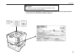
Chapter 1 Safeguards and Installing the Page Printer Contents of Printer Box and How to Remove Them (1) Power Cord (2) Drum Unit Cover* (3) Toner Kit (toner container, cleaning cloth) (4) User’s manual and CD-ROM including the printer drivers and manuals. Remove the tape used for packaging as shown in the diagram rather than cutting with a cutter. This tape can be reused when repackaging the printer. (1) (2) (3) (4) * This drum unit cover is necessary during maintenance to remove the drum unit.
Unpacking and Inspection How to Remove the Paper Feeder 1-9
Chapter 1 Safeguards and Installing the Page Printer Moving the Printer Note the following items when moving the printer. CAUTION Be sure that two or more people lift the printer. Grasp the handholds . indicated in the figure below and lift carefully so as not to hurt your back. Be sure to lift the printer gently, keeping it horizontal, to prevent toner from soiling the inside of the printer. When transporting the printer a long distance, contact the your dealer from which you purchased the printer.
Names of Parts Names of Parts Front View/Side View Power Switch Paper Full Sensor Face-Down Output Tray Vent Paper Stopper Control Panel Connector for Optional Feeder* MP (Multi-Purpose) Tray Side Cover Front Cover Paper Feeder Side Cover Handholds Upper Paper Feed Cassette Lower Paper Feed Cassette Paper Feeder Face-Up Output Tray Handholds * To prevent static electricity, be sure to cover the optional feeder connector not being used with the protective caps supplied with the printer.
Chapter 1 Safeguards and Installing the Page Printer Rear View Memory Card Slot Interior View Option Interface/Hard Disk Unit Slot Cover (OPT2) Toner Container Release Lever (Green) Parallel Interface Connector* ( ) Top Cover Toner Container Power Cord Connector Drum Unit Release Lever (Grey) Option Unit (Service use only) Lock Lever Connector (Green) Drum Unit Fuser Unit Rear Panel Serial Interface (RS-232C/RS-422A) Connector* (IOIOI) Charger Unit Option Interface Slot Cover (OPT1) Cleaning Knob (
Setup and Connections Setup and Connections Set up the printer according to the following steps. 1. 2. 3. 4. 5. 6. 7. 8. 9. 10. 11. 12. 13. Install the printer on the paper feeder. ............................................................................ Page 1-14 Open the top cover. ........................................................................................................ Page 1-15 Install the toner container. ..............................................................................
Chapter 1 Safeguards and Installing the Page Printer 1. Install the printer on the paper feeder. Align the installation holes on the bottom of the printer with the positioning pins on top of the paper feeder and slowly lower the printer into place. Check that the connector on top of the paper feeder is properly connected to the connector on the bottom of the printer. Casters (CA-28) capable of being mounted on the paper feeder are available as an option.
Setup and Connections 2. Open the top cover. Remove the packing tape stuck to the printer and gently lift the top cover as far as it will go.
Chapter 1 Safeguards and Installing the Page Printer 3. Install the toner container. 1. Take the toner container from the toner kit. Shake the toner container with the protective seal facing up as shown in the figure five times or more to thoroughly mix the toner inside. Toner Container Shake five or more times. Protective Seal 2. Carefully peal off the protective seal.
Setup and Connections 3. Check that the two toner container release levers are positioned to the right (released) as shown in the figure. If not positioned to the right, slide them to the right until they stop. Toner Container Release Levers (positioned to right) 4. Align the ends of the toner container with the grooves to the left and right inside the printer as shown in the figure and install.
Chapter 1 Safeguards and Installing the Page Printer 5. Check that the toner container is installed in the correct position, and push forcefully on the top of the toner container. 6. After the toner container is installed, set the two toner container release levers to the left position (fixed). Toner Container Release Levers (Be sure to set to the left and fix the container in place.
Setup and Connections 4. Close the top cover. Close the top cover. Top Cover 5. Adjust the paper guide on the paper feed cassette. The paper feed cassette attached to the paper feeder located at the bottom of the printer can be used to supply standard paper from A5 size up to ledger size by adjusting its paper guide and paper stopper position. The paper feed cassette is shipped from the factory set to A4 or letter. The positions for each paper size are indicated inside the paper feed cassette.
Chapter 1 Safeguards and Installing the Page Printer Paper feed cassette position Paper Guide : Paper Size Indicator Position Note: Be sure to remove the size indicator plates which are temporarily attached before using the printer. Paper Stopper Paper Guide 1-20 Front Side 1. Pull out the paper feed cassette until it stops. 2. Open the paper feed roller located on the right side of the cassette until it stops as shown in the figure. 3.
Setup and Connections Paper Limit Indicator Paper Stopper 3. 1. Paper Feed Cassette 4. 2. Paper Guide Do not touch the rubber part of the paper feed unit.
Chapter 1 Safeguards and Installing the Page Printer 6. Add paper. Try as much as possible to use fresh paper which has just been opened. Paper which has been stored long periods contains moisture and may result in sheets sticking together and/or paper jams. For specifications on the paper which can be used with this printer, please refer to Appendix B Paper Selection. 1. 1. Square the edges of the paper and insert into the paper feed cassette as shown in the figure.
Setup and Connections 3. Close the paper feed cassette. Paper is added to the second paper feed cassette in the same way. 4. Size indicator plates are also supplied. Place these on the front of the cassette according to the paper size inside to make it easy to know the current paper size.
Chapter 1 Safeguards and Installing the Page Printer 7. Open the paper stopper on the face-down tray (if required). Raise the paper stopper on the face-down tray. Paper Stopper 8. Open the face-up output tray (when the tray is being used). Use the face-up output tray when you wish paper to be stacked with the printed side facing up (reverse order). The face-up output tray is located on the left side of the printer. Use it by opening as shown in the figure.
Setup and Connections 9. Connect the printer to the computer. CAUTION Before performing this step, be sure to turn off the printer's power switch and unplug the power plug from the power outlet. Failure to do so may result in electric shock. A standard Centronics parallel interface connector ( ) and RS-232C/RS-422A serial interface connector (IOIOI) are located on the rear side of the printer. For pin connections, please refer to Appendix C.
Chapter 1 Safeguards and Installing the Page Printer Parallel Interface Connection 1. Plug one end of the printer cable into the connector on the printer marked with a symbol. 2. Close the clips on both sides to fix the connector in place. (parallel) Clips Printer Cable 3. Plug the other end of the printer cable into the computer’s parallel (Centronics) interface connector. This connector is usually marked PRINTER. For details, please refer to the hardware manual for the computer.
Setup and Connections 10. Attach the power cord. CAUTION Be sure the printer's power switch is turned off. Note______________________________________________________________________ Only use the power cord supplied with the printer. 1. Plug the power cord into the power cord connector on the rear side of the printer. Power Cord Connector Power Cord 2. Connect the other end of the power cord into a power outlet. WARNING Be sure to connect the ground wire of the printer to ground.
Chapter 1 Safeguards and Installing the Page Printer 11. Test the printer. Use the following procedure to test the printer and print out a status page indicating factory settings. For details on the indicators and keys on the printer’s control panel, please refer to Chapter 2 Control Panel. 1. Turn on the printer's power switch. It does not matter whether the computer's power is on or off. Self test will be displayed in the message display of the printer.
Setup and Connections 12. Test the interface with the computer. In order to check that the printer and the computer are properly connected you must print by sending an actual command from the computer. 1. Turn on the printer's power switch and turn on the computer’s power as well. 2. Wait until the message display switches from Self test to Ready. 3. Check that the ON LINE indicator is lit. If it is not lit, make it light by pressing the ON LINE key. 4.
Chapter 1 Safeguards and Installing the Page Printer 13. Install the printer driver. A CD-ROM containing a printer driver for Windows (Windows 3.1, Windows 95/98 and Windows NT 3.51/4.0) is supplied with this printer. Once this printer driver is installed on the computer, it is possible to make various settings for this printer from within Windows applications. It is also possible to control options and printing from within Windows.
Setup and Connections 3. The printer folder will open. Double click on “Add printer.” Windows 95 Windows 98 4. The Printer Wizard screen will appear. Click on “Next >.” 5. A screen for selecting the printer to be connected will appear. Select the most printer and click on “Next.” 6. Next, “Click the manufacturer and model of your printer....” screen will appear. At this point, select “Have Disk…” located at the lower right. (See the figure for Step 7.) 7.
Chapter 1 Safeguards and Installing the Page Printer 8. Select “DP-3600,” click on “Next >,” and follow the on-screen instructions to install. Once the driver has been properly installed, the printer icon will be added to the printers folder. Note______________________________________________________________________ When printing under Windows 95/98, be sure to set the emulation of this printer to HP LJ 5M/5Si (default setting).
Setup and Connections Installing Under Windows 3.1 1. Insert the supplied CD-ROM into the CD-ROM drive of the computer. 2. Double click on the “Control Panel”. 3. Double click on “Printers.
Chapter 1 Safeguards and Installing the Page Printer 4. Click on “Add >>.” 5. A screen for “List of Printers:” will appear. From the choices, click on “Install Unlisted or Updated Printer.” 4. 5.
Setup and Connections 6. Click on “Install….” 7. The install printer menu will appear. Enter “[CD-ROM Drive Name]: \” and click on “OK.” 6. 8. Select “DP-3600” from the printers displayed and click on “OK.” Once the driver has been installed, close the Control Panel by clicking on “Close.
Chapter 1 Safeguards and Installing the Page Printer The Multi-Purpose Tray The multi-purpose tray is incorporated on the right side of the printer. It can be used in one of two modes: first mode or cassette mode. The multi-purpose tray can hold about 100 sheets of paper (0.1 mm thickness). First Mode (Automatic Manual Feeding) The printer automatically feeds any paper placed on the multi-purpose tray even if another paper source is selected.
The Multi-Purpose Tray Feeding from the Multi-Purpose Tray 1. Open the multi-purpose tray as shown in the figure. Multi-purpose tray 2. Open the sub tray and adjust the paper guides according to the width of the paper to be fed. Paper guides Sub tray Note: The paper guides must be set to the widest position when closing the multi-purpose tray.
Chapter 1 Safeguards and Installing the Page Printer 3. Check that the message Ready is displayed in the printer's message display, and that the ON LINE indicator is lit. 4. Set the paper source to the multi-purpose tray by pressing the FEED key until the message display indicates MP tray. The multi-purpose tray indicator on the control panel will flash, and Add paper will be displayed. 5. Press the MODE key. Then use + or – keys to display Paper handling 6.
The Multi-Purpose Tray Cassette Mode 1. Press the MODE key to display Paper handling 2. Press the 4 (Form Feed) key to display >MP tray mode. 3. After pressing the ENTER key, the mode display is changed by pressing the + and – keys. Display Cassette and then press the ENTER key. >. >MP tray mode Cassette 4. Press the EXIT key. 5. Insert the paper so that it is aligned straight in the tray as far as it will go. About 100 sheets 2 (0.1 mm thickness, 80 g/m ) can be inserted at one time.
Chapter 1 Safeguards and Installing the Page Printer Feeding Envelopes Envelopes should be fed face up. Be sure to set the print direction from the Mode Select Menu. Insert the envelopes in the tray as far as they will go. Do not load envelopes above the paper limit mark. Paper limit mark Envelopes For details on suitable envelope paper quality and shape, see Appendix B. Be sure to use suitable envelopes as print quality may be reduced.
Expanding Memory Expanding Memory The printer comes standard equipped with 16 MB of main memory. However, more complex pages can be printed and processing speed increased by expanding the printer’s memory. There are two slots available in the printer for expanding memory. (One 16 MB SIMM is installed in one of the slots when the printer is shipped from the factory.) Printer memory can be expanded to up to 64 MB by installing optional extended memory chips (SIMMs) in these slots.
Chapter 1 Safeguards and Installing the Page Printer The description given below is intended for service personnel. Precautions on the Handling of Extended SIMMs Static electricity which may accumulate in the human body through walking on carpets or other such surfaces is the enemy of SIMMs loaded with many semiconductor chips. Pay attention to the following things before installation to protect memory chips against damage from static electricity.
Expanding Memory Installing SIMMs Insert the SIMM or SIMMs into the dedicated sockets on the printer's main board. WARNING Take precautions that no foreign substances such as metal chips or liquid get inside the printer during the installation process. Operation of the printer during the presence of a foreign substance may lead to fire or electric shock. CAUTION Be sure to turn off the printer's power and disconnect all cables when installing SIMMs in the printer.
Chapter 1 Safeguards and Installing the Page Printer 1. Turn off the printer's power and disconnect the power cord and all cables connected to the printer. 2. Remove the six screws on the printer's rear cover, and remove the rear panel. There are two sockets for installing SIMMs located on the main board.
Expanding Memory 3. Remove the SIMM or SIMMs from the package. À Insert the connector end of the SIMM into the socket. Á Carefully push the board upright until it snaps into place. Make sure that the catches at the ends of the socket fit into the holes at the ends of the SIMM board. À Á SIMM Catch Socket Note______________________________________________________________________ SIMMs may be installed in either slot regardless of their memory capacity.
Chapter 1 Safeguards and Installing the Page Printer To remove a SIMM, carefully pull the end catches slightly outwards and tilt the SIMM as shown, then pull the SIMM out of the socket. 4. After the SIMMs have been installed, reattach the rear cover on the printer and tighten all six screws securely. After SIMMs have been installed in the printer, use the following procedure to check that installation has been performed properly.
Expanding Memory Testing Extended Memory 1. Check that the power switch is off, plug the power cord into the printer, and turn the power on. 2. Wait for the printer's ON LINE indicator to light and the message display to read Ready, and press the STATUS key. 3. If installation has been performed properly, a status page will be printed. Check the Memory in the upper right. Information on the SIMMs installed in slot 1 and slot 2 is shown here. There is no problem if total memory has increased.
Chapter 2 Operating the Page Printer This chapter explains the printer's control panel and operating procedures. It also covers operations which use the memory card. Control panel ...................................................................... 2- 2 Operating Procedures......................................................... 2- 11 Mode Selection Menu ......................................................... 2- 24 Configuring Interfaces.........................................................
Chapter 2 Operating the Page Printer Control Panel The printer control panel consists of indicators, a message display, and various keys.
Control Panel Message Display The message display displays the printer's operational mode. Messages which are displayed and their meaning are given in the table below. Message Meaning Self test The printer is self-testing and warming up after power-up and is not ready to print. Please wait The printer is warming up and is not ready to print. Ready The printer is ready to print Processing The printer is processing print data or in the middle of printing. Waiting The last page remains unprinted.
Chapter 2 Operating the Page Printer Interface Indicator The interface indicator indicates the interface over which data is currently being received or was last received. When an optional interface such as a network interface is installed in the printer, this indicator displays the information in the table below depending on the interface used.
Control Panel Paper Size Indicator The paper size indicator indicates the paper size of the cassette currently installed in the printer (factory setting is A3) or the paper size currently set for the multi-purpose tray. During printing the paper size specified by the computer in data being sent to the printer will be displayed.
Chapter 2 Operating the Page Printer Copy Indicator Indicates the number of copies set in the current interface (001 – 999), and the number is reduced as printing proceeds. Indicator Refer to the table below for the names and meanings of indicators on the control panel. Indicators on the Control Panel Indicator 2-6 Name Description Face-down tray indicator Flashing: Indicates that paper is jammed near the facedown output tray.
Control Panel Indicator Name Description Multi-purpose feed indicator Flashing: Indicates that there is no paper in the tray or that paper is jammed near the multi-purpose tray. Lit: Indicates when paper is fed from the multi-purpose feed tray. Optional paper feeder indicator Duplex printing indicator ON LINE DATA ATTENTION Flashing: Indicates that there is no paper in the optional envelope feeder (EF-100); or that paper is jammed near the paper feed opening.
Chapter 2 Operating the Page Printer About the LED Indicator for the Paper Feed Cassettes The size indicator plate on the front of the paper feed cassettes is illuminated by LED. This LED indicates the status of the cassettes as follows depending on whether it is on, off or flashing. LED Status Flashing quickly Flashing slowly Lit Out Paper size indicators 2-8 Meaning Paper feed from this cassette is jammed. This cassette is out of paper. This cassette is currently selected.
Control Panel Control Keys ON LINE DATA ATTENTION CONTINUE FORM FEED 3 CANCEL STACK FEED INTERFACE RESOLUTION SIZE COPIES EXIT ENTER MODE STATUS The functions of each key are given in the table below. Key Function ON LINE key Pauses and restarts printing. Data can be sent even while printing is paused. (See page 2-16.) CANCEL key (1) This key can be used to cancel mode selection during mode selection or cancel printing during printing. (See page 2-17.
Chapter 2 Operating the Page Printer Key Function CONTINUE/ 3key (1) This key forcibly cancels errors and resume printing when printing is halted due to errors such as memory overflow. (2) This key functions as the 3key during mode selection. It moves upward in the mode select menu and moves the cursor left. EXIT/MODE key (1) This key interrupts settings when pressed during mode selection. (See page 2-23) (2) This key is used to start and end the next mode selection and make settings.
Operating Procedures Operating Procedures This section explains basic operations of the printer and procedures leading up to and including printing. Operating Precautions · · Do not turn off power during printing. This may result in a paper jam or damage to the printer. · · Do not move the printer during printing. · · · · Do not open covers on the printer or covers of optional equipment or open the paper feed cassette during printing.
Chapter 2 Operating the Page Printer Switching Power On Check that the power cord is securely plugged in at both ends. Check that the printer is connected to the computer (See page 1-28). 1. Push the power switch to the ON ( | ) position. Power Switch 2. Wait for the printer to warm up. During warm-up the message display indicates Self test. 3. At the end of the warm-up period, the ON LINE indicator lights, and the message display indicates Ready. The printer is now ready to print.
Operating Procedures Basic Printing Operations The flow of basic operations to print is given below. Keys on the control panel are explained after that. For details on using the MODE key, be sure to read the section “Mode Select Menu” at the end of this manual in conjunction with this section. 1. Use the MODE key to set an emulation for the printer which conforms to the software being used. This printer is shipped from the factory with emulation set to HP LJ 5M/5Si. 2.
Chapter 2 Operating the Page Printer Selecting the Output Tray Printed paper can be output on either the face-up output tray or the face-down output tray. Selecting the face-up output tray will cause paper to be stacked with the printed surface facing up. Selecting the facedown output tray will cause paper to be stacked with the printed surface facing down. Normally it Is more convenient to use the face-down output tray.
Operating Procedures Feed Selection Use the FEED key to select whether to feed paper from one of the paper feed cassettes or from the multi-purpose tray. If optional paper feeders (ST-1000 or EF-100) are installed, any of these can also be selected. The FEED key can be used whenever the message display indicates Ready or Add paper. Press the FEED key.
Chapter 2 Operating the Page Printer MP (multi-purpose) tray indicator Cassette indicator Switching Online/Offline After printing starts, it is possible to interrupt printing to check whether the print job is coming out as anticipated. Pressing the ON LINE key during data processing will cause the ON LINE indicator to go out and pressing it during printing will cause the printer to stop after the page currently being printed is finished.
Operating Procedures Canceling Printing Perform the following procedure when you wish to cancel printing after it has begun. 1. Check if the message Processing is displayed in the message display. 2. Press the ON LINE key to take the printer offline. 3. Perform the necessary procedure on the computer to halt printing. 4. Press the CANCEL key. 5. The message Print Cancel? will appear in the message display and the interface to be canceled will be displayed.
Chapter 2 Operating the Page Printer Press the CANCEL key again if you wish to stop the cancellation of printing. Press the ON LINE key to put the printer back online to continue with other print jobs. Notes_____________________________________________________________________ · · 2-18 Canceling data from the computer using the CANCEL key will restore temporary settings to their default values. (The same status resulting from executing the PRESCRIBE 2e RES command.
Operating Procedures Status Printout It is possible to print out and check the printer's current status including unit emulation, font, printing range, and memory usage. 1. Check that the ON LINE indicator lit and that the message Ready is displayed in the message display. 2. Press the STATUS key. The message display will read Processing, and a status page will be printed. After it is finished printing, the message display will return to Ready.
Chapter 2 Operating the Page Printer Sample Status Page 1 2 4 5 3 6 7 8 9 2-20
Operating Procedures 1 — Software version This information shows the software version and date of issue of the printer. 2 — Hardware information This information shows the currently selected paper feed source (indicated by an asterisk), paper size, paper type, and main settings of the printer. 3 — Page information This information shows the currently selected resolution and number of copies.
Chapter 2 Operating the Page Printer 8 — Fonts at startup (for each interface) This shows the font automatically selected when the printer starts up (default font). It is possible to set different fonts for the parallel interface and the serial interface. The figure on page 2-20 shows default settings. The font is set to "1" (Courier bitmap font). This also shows font information similar to the column below if an optional interface is installed.
Operating Procedures Form Feed Depending on the software, the message Waiting may be displayed in the message display when you get to the end of a print job. This occurs when the software does not issue a final form feed to the printer indicating the end of the print data. If you wait awhile, FormFeed TimeOut will be displayed and the last page will be printed automatically. Pressing the FORM FEED key allows you to finish printing immediately. 1. Check if the message display reads Waiting. 2.
Chapter 2 Operating the Page Printer Mode Selection Menu This section explains the menu hierarchy used for all menus which can be set and selected using the MODE key. The MODE key can be used to display all of the menus in the table below. This mode selection menu conforms to the menu hierarchy given at the end of this manual. Pressing the MODE key initially displays menus at the top of the hierarchy. Use the + and – keys to move between menus in the same level.
Mode Selection Menu Menu Description Default Setting Number of copies Set the number of copies to be printed. This can be set up to 999. 001 Emulation > HP LJ 5M/5Si Font > Switches the printer emulation. The mode can be further set if KC-GL emulation is set. Selects the print font. Page set Size reduction settings [See page 29] [CS] ® [CS] Page orientation Print direction settings [See page 29] Portrait Opt.
Chapter 2 Operating the Page Printer Menu Others Description > Default Setting The following sub-menus can be displayed by pressing the 4 key and then the + or – key. Message language setting Automatic form feed timeout setting Sleep timer setting [See page 2-56.] Receive data damping [See page 2-57.] Print a list of resident fonts Printer reset Line feed setting [See page 2-29.
Configuring Interfaces Configuring Interfaces The printer is equipped with both a parallel and serial interface. Independent settings can be made for each interface. Optional interfaces can also be installed. To configure each interface, press the MODE key and use the + or – key to select the interface you wish to make settings for. Note______________________________________________________________________ This interface selection does not select which interface data will be received from.
Chapter 2 Operating the Page Printer Emulation Selection The following emulations can be selected for this printer. The emulation selected is stored even while the printer's power is off. Line printer IBM Proprinter Diablo 630 EPSON LQ-850 HP LJ 5M/5Si (Default setting) KPDL KC-GL KC-GL Emulation The following settings can be made from the sub-menu when KC-GL emulation is selected.
Reduction (Page Set) Reduction (Page Set) Make settings on the page set menu to print at a reduced size. This menu is used to set the source paper size and the paper size to use after reduction. These settings can be made from within programs or files using the PRESCRIBE 2e SPSZ command. Notes_____________________________________________________________________ · · Printed results when making reductions differ from equivalent size printing.
Chapter 2 Operating the Page Printer It is possible to set the following paper sizes (envelope) when using the PRESCRIBE 2e SPSZ command. The message display will show the messages given in the following table. Source Size-Target Size Combinations Source Size Indicator Target Size Indicator Reduction/Enlargement Ratio CS CS CS 98% 100% 98% LG Legal size (8.5 ´ 14 inches) LG LG 98% 100% 98% LT Letter size (8.5 ´ 11 inches) LT A4 LT 98% 100% 94% 98% LD Ledger size (12 ´ 15.
Reduction (Page Set) Source Size Indicator Target Size Indicator Reduction/Enlargement Ratio A4 (21 ´ 29.7 cm) A4 LT B5 A5 A4 98% 100% 94% 86% 70% 98% B4 (25.7 ´ 36.4 cm) B4 B5 A4 B4 98% 100% 70% 81% 98% A3 (29.
Chapter 2 Operating the Page Printer RAM DISK A RAM DISK can be set up as a virtual media device by setting a given amount of the total printer memory as the RAM DISK. This can then be used for reading and writing data just as with a memory card or as a virtual mail box function (see page 2-34). Note however that data written to the RAM DISK is lost if the printer is reset or its power turned off. RAM DISK settings can be made from the printer's control panel.
RAM DISK 5. Press the ENTER key again, and change the RAM DISK size using the + or – key. It is not possible to make a setting that exceeds total printer memory. The default value for the RAM DISK is the total printer memory minus 9 MB. This parameter may be set anywhere from 01 to 55 depending on the available printer memory. Press the EXIT key if you want to cancel the setting. 6. Once the desired RAM DISK size is displayed, press the ENTER key. 7. Press the EXIT key.
Chapter 2 Operating the Page Printer Virtual Mail Box (VMB) The Virtual Mail Box (VMB) function is a mail box function for the printer which does not require a physical mail box to be attached to the printer. The virtual mail box function can be used when RAM DISK mode is On or when an optional hard disk unit is installed on the printer. This manual describes how to use the virtual mail box with a RAM DISK.
Virtual Mail Box (VMB) Outputting to a VMB When sending data to a virtual output tray set within the RAM DISK, make this setting from the printer driver. With this setting, data can be sent by specifying the desired virtual output tray number. It is also possible to assign a name to a virtual output tray and send data by specifying that name. (For details on this setting, please refer to the help documentation for the printer driver.
Chapter 2 Operating the Page Printer 4. Display the VMB data you want to print. Pressing the ENTER key will cause Processing to be displayed and the data will be printed. Print Accumulated VMB Data with a Password This function prints VMB data protected by a password which has accumulated in a virtual output tray. 1. Display >Print VMB data Tray. The VMB tray number will appear in the location marked by #'s below, while the VMB tray name will appear in the location marked by %'s.
Virtual Mail Box (VMB) 5. Press the ENTER key once the correct password is entered. Processing will be displayed and the data will be printed. If the password was incorrect, an error message will be displayed. (See page 5-11.) Pressing the CONTINUE key will return the printer to Ready status. Note that the password entered here is reset (returns to 00001) when this mode is exited. Print VMB Accumulated Data List This feature prints a list of VMB data accumulated in the RAM DISK. 1. Display >List of VMB.
Chapter 2 Operating the Page Printer An actual VMB list printout will differ slightly from sample given above. Information regarding virtual output trays which are set will be displayed in the virtual mail box list. A mark is shown with the bin number for virtual output trays which contain data. If a password is set for a virtual output tray, there is no barcode shown for that virtual output tray. Also, "FULL!!" will be shown for virtual output trays for which there was an error when data was sent to them.
Virtual Mail Box (VMB) Operations for Using a Barcode Reader If an optional barcode reader (Barcord Reader DP-28/3600 Series) is connected to the printer, it is possible to print data within a virtual output tray using the barcode in the list. Select the barcode for "Output (1)" in the upper right using the barcode reader and then select the barcode for the virtual output tray you want to print.
Chapter 2 Operating the Page Printer Memory Card This printer is equipped with a memory card slot. This allows, for example, the use of fonts other than internal fonts by using an optional font card. If a JEIDA Ver. 4.2/PCMCIA Ver. 2.1 memory card is used, it is possible to read, write and delete data and format the memory card. Note______________________________________________________________________ Only 32 MB or less flash or S-RAM type memory card conforming to JEIDA Ver. 4.2/PCMCIA Ver. 2.
Memory Card Notes_____________________________________________________________________ Follow the precautions below when handling a memory card. · · · · · · · · · · A memory card is sensitive to static electricity. Before handling a memory card, be sure to eliminate any static electricity which may have built up on your body or clothing by touching a metallic object. Use a flash memory card or S-RAM memory card conforming to JEIDA Ver. 4.2/PCMCIA Ver. 2.1 which are approved by us.
Chapter 2 Operating the Page Printer Note that only reading fonts and printing a list of partitions are possible when a font card is inserted. The following sections explain each of these operations. Each operation is described below. Reading Fonts from a Memory Card Fonts can be read into the printer's internal memory from an optional font card. The font read can then be selected from the printer's control panel. A font card is automatically read into the printer when the printer's power is turned on.
Memory Card Reading Macros from a Memory Card Macro data on a memory card can be registered on the printer. Registered macro data can be used just like macro data located in printer memory. If a memory card already containing macro data is inserted in the printer, that macro data will be read into the printer automatically when the printer's power is turned on. The operation described here is performed when a memory card is inserted while the message display reads Ready.
Chapter 2 Operating the Page Printer Notes_____________________________________________________________________ · · If the name of a macro on the memory card is the same as that in printer memory, the macro data on the memory card with the conflicting name will not be registered. Registered macro data will be lost if the memory card is pulled out. Re-execute >Read macro if this happens.
Memory Card Writing Data (Partitions) to a Memory Card Data sent from the computer can be written on a memory card. Data written on the card can be read into printer memory by key operations from the control panel of the printer. Assuming the card has enough memory capacity, up to 127 partitions can be written on a single card. Partitions written on the card are automatically assigned names, which can be checked by printing out a partition list.
Chapter 2 Operating the Page Printer 5. Check that the message display has changed to Waiting and press the FORM FEED key. The printer will automatically print the data just written (example below). This printout can be used to check the name (partition name) under which data was written and confirm that it was written properly.
Memory Card Deleting Data from a Memory Card It is possible to delete data names on a memory card one at a time. Check that the memory card can be written (that write-protection is released). 1. Bring up the menu >Delete data on the message display. This display only appears if the memory card contains data. 2. Press the ENTER key. ? will flash and a data name will appear after it. The ? will flash, and a data name will appear. >Delete data ? (data name) 3.
Chapter 2 Operating the Page Printer 1. Bring up the menu >Format on the message display. 2. Press the ENTER key. ? will appear. 3. Pressing the ENTER key again will cause Processing to appear in the message display and the memory card will be formatted. The printer will print memory card formatting information (example below) after initialization is finished. Use this to check that the memory card has been formatted properly.
Memory Card Printing a List of Data Names (Partitions) This operation prints the contents (data names, data size, etc.) of the memory card inserted in the memory card slot. 1. Bring up the menu >List of Partitions on the message display. 2. Press the ENTER key. ? will appear. Press the CANCEL key to cancel printing. 3. Pressing the ENTER key again will cause printing to start. After this information is printed, the message display will return to Ready.
Chapter 2 Operating the Page Printer Note______________________________________________________________________ "Remaining Size" in the partition list indicates the amount of remaining memory on the memory card. Since the system uses about 70 bytes to write a piece of data on the memory card, the actual available memory on the card is a little less than that displayed.
Setting the Paper Type Setting the Paper Type This printer is capable of printing under the optimum setting for the type of paper being used. Setting the paper type for the paper source from the printer's control panel will cause the printer to automatically print in the mode best suited to that type of paper. This allows you to easily achieve highquality printing results. A different paper type setting can be made for each paper source including the multipurpose tray.
Chapter 2 Operating the Page Printer Making Settings The following describes the procedure for setting the paper type using the Recycled type and Cassette 1 as examples. 1. Display Paper handling > on the printer's Mode Select Menu and press the 4 key. Then use the + and - keys to display the Cassette 1 type. Paper handling > >Cassette 1 type Plain 2. Pressing the ENTER key will cause a ? to flash. Press the + or - keys to display Recycled.
Setting the Paper Type Paper type user setting The following describes the procedure used to set a user-defined paper type for the printer. Eight custom user settings may be registered. After having been set, any of these may be called up when setting the paper type for a paper source. 1. Display Paper handling > on the printer's Mode Select Menu and press the 4 key. Then use the + and - keys to display >Custom setup. Paper handling > >Custom setup > Custom # 2.
Chapter 2 Operating the Page Printer 3. Press the 4 key after selecting the paper type you want to customize. Pressing the + or - keys will cycle through a display of the submenus given in the table below. Submenus displayed Selection parameters Description >>Paper weight Light(Thin) Normal (default) Heavy (Thick) Sets the paper thickness >>Fuser mode Vellum Low Middle (default) High Sets the temperature for the fusing unit.
Setting the Paper Type 4. Pressing the ENTER key will cause the ? to disappear. Pressing the EXIT key will exit the setting. The same procedure can be used to set the parameters on other submenus. Note that the setting status for paper weight and fuser mode used for each paper type is as given in the table below. In addition, all paper type settings made using Custom setup can be reset to the default values shown in the table below using the >Reset custom setup menu.
Chapter 2 Operating the Page Printer Sleep Timer Setting This printer is equipped with a sleep timer function for conserving energy in cases where there has been no operation from the control panel or data has not been received for a predetermined period of time. The sleep timer can be set anywhere from 0 to 120 minutes in 5-minute increments. Setting the sleep timer to 0 turns it off. The sleep timer is set at the factory to 30 minutes.
Dumping Received Data Dumping Received Data It is possible to print data received by the printer as hexadecimal code for the purposes of debugging programs and files. 1. Pressing the ENTER key once while >Print HEX-DUMP is shown on the will cause a ? to flash. 2. Send data to be dumped to the printer while the ? is flashing. 3. Pressing the ENTER key again will print the corresponding pages of dumped data.
Chapter 2 Operating the Page Printer KIR 2 Level This printer incorporates the KIR 2 smoothing function. KIR 2 provides high quality printing by providing a software-type improvement to the resolution. Print a status page to find out the current mode. The KIR 2 setting is Off. The KIR 2 setting is On (Default setting). Note______________________________________________________________________________ · · 2-58 Set the print density to “ 03 ” when setting the KIR 2 mode.
KIR 2 Level Status page KIR 2 Checking Lines KIR 2 Setting Description Optimized stripes The current KIR 2 setting is optimal. Dark vertical stripes The KIR 2 mode currently set is too strong. Set the KIR 2 mode to Off. (See the Mode Select Menu at the end of this manual.) White vertical stripes The KIR 2 mode currently set is too weak. Set the KIR 2 mode to On. (See the Mode Select Menu at the end of this manual.
Chapter 2 Operating the Page Printer Ecoprint Mode The Ecoprint enables you to reduce the amount of toner consumed on the page so as to save your printing costs. The factory-setting is off. Ecoprint is Off (default) Ecoprint is On Notes_____________________________________________________________________ · · 2-60 Ecoprint status varies depending on the feed direction of the paper and the print direction. The Ecoprint setting has no effect on the print speed.
Resource Protection Resource Protection When you switch from the HP LJ 5M/5Si emulation to another, all downloaded fonts and macros are lost. Resource protection preserves these PCL resources in memory so that they are intact when you change the emulation back to HP LJ 5M/5Si. By using the printer's >Resource prot., you can select from two resource protection modes as follows: >Resource prot. Permanent In this mode, the printer stores fonts, macros, symbol sets, etc.
Chapter 2 Operating the Page Printer Adjusting the Print Density If necessary, the print density can be adjusted from the Mode Select Menu. The required print density can be selected from five different steps (01 – 05). The factory setting is 03, and there is normally no need to alter this setting. When using the KIR 2 function, please use the “ 03” setting. For details on adjusting the KIR 2 mode, see page 2-58.
Setting the Audio Warning (Buzzer) Type of Error and Corresponding Audio Alarm (Buzzer) Priority Error Message Alarm Frequency Remarks High Paper jam short beeps – Replace Toner Clean printer short beeps – Clean printer Press CONTINUE short beeps – Option stacker path error short beeps * Option Stacker paper full short beeps * Face-down tray paper full short beeps – Option tray paper full ## short beeps * Remove paper Option tray ## short beeps * Remove Opt.
Chapter 2 Operating the Page Printer Priority Error Message Alarm Frequency Remarks Print overrun Press CONTINUE short beeps – KPDL Error ## Press CONTINUE short beeps – MEMORYCARD err## Press CONTINUE short beeps * HARDDISK error## Press CONTINUE short beeps * RAM DISK error Press CONTINUE short beeps * Opt.
Setting the Audio Warning (Buzzer) The alarm will continue to sound while the error condition continues (if the printer is in the sleep mode, the alarm will be silent for that period alone). The alarm will cease to sound, however, when the CANCEL key is pressed. To rectify the various error conditions listed above, please refer to Chapter 5 of this manual, or to the operating manuals accompanying the various optional equipment.
Chapter 3 Fonts This chapter describes the types of fonts you can use with the printer, including the printer’s resident and KPDL fonts, and symbol sets. Bitmap and Scalable Fonts........................................................ 3-2 List of Fonts ............................................................................... 3-3 Symbol Set ................................................................................
Chapter 3 Fonts Bitmap and Scalable Fonts A font is a set of characters of a particular design. The design is referred to as a typeface. Several characteristics identify a font. These include the font type (bit map or scalable), symbol set, spacing, pitch, height, style, stroke weight, and typeface family. The printer provides two types of resident fonts: bitmap fonts and scalable (outline) fonts. Also, fonts may be downloaded to the printer’s memory or optional harddisk from a memory card or disk.
List of Fonts List of Fonts This section contains a full list of the printer’s resident fonts. You can print the same font list from the printer by using the printer’s control panel key. To print a list of fonts, refer to Mode Select Menu, List of Resident fonts. Bitmap Fonts The printer has 80 resident bitmap fonts. Note that all resident bitmap fonts include the letters BM in the typeface name. Scalable Fonts The printer has 45 resident scalable fonts.
Chapter 3 Fonts Resident Scalable Fonts (1) 3-4
List of Fonts Resident Scalable Fonts (2) 3-5
Chapter 3 Fonts KPDL Fonts (1) 3-6
List of Fonts KPDL Fonts (2) 3-7
Chapter 3 Fonts Symbol Set A symbol set is the set of alphabetical and numerical characters and symbols the printer prints. Each character is assigned to a particular character code. The page printer offers not only a large selection of bitmap and scalable fonts but also a large selection of symbol sets (also referred to as character sets). This is because the printers the page printer emulates have a number of their own symbol sets for printing in different languages and other purposes.
Symbol Set Table 3.1. Bitmap Fonts Symbol sets SSET value SSET ID Symbol set 4 0D ISO 60: Norway 9 0I ISO 15: Italian 14 0N ECMA-94 Latin 1 19 0S ISO 11: Swedish 21 0U ISO 6: ASCII 37 1E ISO 4: U.K.
Chapter 3 Fonts Table 3.2. Scalable Fonts Symbol sets SSET value SSET ID Symbol set 4 0D ISO-60 Norway 9 0I ISO-15 Italian 14 0N ECMA-94 Latin 1 19 0S ISO-11 Sweden 21 0U ISO-6 ASCII 37 1E ISO-4 U.K.
Symbol Set SSET value SSET ID Symbol set 309 9U Windows 330 10J PS text 341 10U IBM PC-8 373 11U IBM PC-8 (D/N) 394 12J Macintosh 405 12U IBM PC-850 501 15U Pi font 565 17U PC-852 Latin 2 620 19L Winbalt 629 19U Windows Latin 1 853 26U PC-775 3-11
Chapter 4 Maintenance This chapter explains how to maintenance the printer. This only covers replacing the toner container and cleaning parts such as the main charger unit and paper feed unit. Toner Container Replacement..........................................4- 2 Cleaning............................................................................
Chapter 4 Maintenance Toner Container Replacement When there is not enough toner, the printer displays the message “ Toner low” in the message display. Be sure to prepare a new toner container when this message appears. If printing is continued in this condition, the printer will display the message “ Replace Toner Clean printer” and stop when there is no more toner. In this case, printing can be continued by replacing with a new toner kit.
Toner Container Replacement Notes_____________________________________________________________________ · · · · Do not use the toner inside the old toner container. Be sure to distance items such as floppy disks during toner container replacement. Be sure to clean the inside of the printer along with replacing the toner container. For details, see Cleaning on page 4-10. Use of the original toner kits is highly recommended to prevent printer trouble and ensure the long life of the printer.
Chapter 4 Maintenance 2. Slide the toner container release levers to the right until they stop and remove the old toner container. After removing it, take care not to tilt the toner container. Toner Container Release Levers 3. Old Toner Container Cap the old toner container with the cap supplied in the new toner kit. Old Toner Container Push the cap securely in place. (Be careful not to cap the new toner container by accident.
Toner Container Replacement 4. Dispose of the old toner container in the plastic waste bag supplied in the new toner kit so that toner does not scatter. Plastic Waste Bag Old Toner Container CAUTION Do not incinerate toner and toner containers. Dangerous sparks may cause burn. Note______________________________________________________________________ Although the toner container is made from non-harmful, flammable material, be sure to dispose of this waste according to local laws and regulations.
Chapter 4 Maintenance 5. Take the new toner container from the toner kit. Shake the toner container five times or more with the protective seal facing up as shown in the figure in order to thoroughly mix the toner inside. Shake five or more times Protective Seal 6. Carefully remove the protective seal.
Toner Container Replacement 7. Check that the two toner container release levers are positioned to the right (released) as shown in the figure. If not positioned to the right, slide them to the right until they stop. Toner Container Release Levers (Positioned to the right) 8. Align the ends of the toner container with the grooves to the left and right inside the printer as shown in the figure and install.
Chapter 4 Maintenance 9. Check that the toner container is installed in the correct position, and push forcefully on the top of the toner container as shown in the figure. 10. After the toner container is installed, slide the two toner container release levers to the left position (fixed) as shown in the figure.
Toner Container Replacement 11. Close the top cover.
Chapter 4 Maintenance Cleaning Be sure to clean the main charger unit and paper feed unit along with replacing the toner kit. Also be sure to clean the inside of the printer periodically (about once per month) to ensure optimum print quality even if you are not replacing the toner kit.
Cleaning Main Charger Unit Cleaning the Charger Wire Clean according to the following procedure. 1. Open the printer's front cover. Front Cover 2. Pull the cleaning knob (green) located on the main charger unit slowly in and out a few times as shown in the figure. This cleans the charger wire inside the unit.
Chapter 4 Maintenance Cleaning the Grid The main charger unit grid should be cleaned when the toner kit is changed. 1. Take the grid cleaner from protective bag in the new toner kit, and remove the cap. Note______________________________________________________________________ The grid cleaner pad is impregnated with water. Clean this part quickly to prevent the pad from drying out.
Cleaning 2. Attach the grid cleaner to the printer with the pad facing up as shown in the figure. Grid Cleaner 3. After attaching the grid cleaner, slightly lift the main charger unit and repeat the action of slowly pulling the cleaning knob in and out at least five times. This will clean the grid inside the main charger unit.
Chapter 4 Maintenance 4-14 4. When the grid is clean, remove the grid cleaner from the printer and dispose of it. The grid cleaner is not re-usable. 5. Close the front cover. This ends the charger unit cleaning procedure.
Cleaning Paper Feed Unit CAUTION Wait a while after turning the printer’s power to allow the fuser unit to cool (about 20 minutes). Do not touch the fuser unit as this may result in a burn injury. Fuser Unit Print problems such as soiling of the reverse side of printed pages may occur if the paper feed unit becomes dirty. Clean the paper feed unit according to the following procedure. 1. Open the printer's front cover. Front Cover 2.
Chapter 4 Maintenance Lock Lever 3. Grasp the handle on the paper feed unit and slowly pull it out.
Cleaning 4. Clean the saw-toothed seperator next to the transfer roller two or three times as shown in the diagram using the cleaning brush housed in the front panel of the paper feed unit. Return the cleaning brush after you have finished using it.
Chapter 4 Maintenance 5. Wipe the paper dust on the registration roller and any dirt on the paper ramp using the cleaning cloth included in the toner kit. Cleaning Cloth Paper Ramp Registration Roller [Metal] Transfer Roller [Black] Paper Feed Unit Note______________________________________________________________________ Be careful not to touch the transfer roller during cleaning as this may adversely affect print quality.
Cleaning 6. When you have finished cleaning the paper feed unit, push it back in until you feel it catch in place. 7. Turn the lock lever clockwise as shown in the figure to securely lock the feed unit.
Chapter 4 Maintenance 8. 4-20 Close the printer's front cover.
Chapter 5 Troubleshooting This chapter explains how to handle printer problems which may occur. If a problem cannot be corrected, please contact your dealer. General Guide .........................................................................5- 2 Print Quality Problems .............................................................5- 4 Indicators and Messages.........................................................5- 8 Correcting a Paper Jam...........................................................
Chapter 5 Troubleshooting General Guide There are quite a few printer problems which may be corrected by the user. This section explains how to correct these problems. If some kind of printer problem should occur, check the following before concluding the printer is broken. Symptom The printer will not print. Check Items Check the ON LINE indicator. Check the print quality of a status page if one can be printed. Corrective Action Off Press the ON LINE key.
General Guide Symptom Nothing lights on the control panel even when power is turned on and the fan makes no noise. Check Items Check that the power cord is properly plugged into the power outlet. Corrective Action Turn off the printer's power, plug in the power cord securely, and try turning on the printer's power again. Check that the power switch is really in the on position. The printer prints a status page, but data from the computer is not being printed normally. Check the interface cable.
Chapter 5 Troubleshooting Print Quality Problems There are many possible causes of the print quality problems, such as blank output, shown in the table below. The troubleshooting procedure for each type of problem is given below. If the checks explained in this section do not solve the problem, please contact your dealer. Printed Results All-black printout Corrective Action Please contact your dealer.
Print Quality Problems Printed Results Dropouts, horizontal streaks, stray dots Corrective Action Clean the charger wire. Open the printer's front cover and clean the charger wire using the green cleaning knob. (See Chapter 4.) Black or white vertical streaks Check the message in the message display. If the Toner low message is displayed and the toner indicator is flashing. (See Chapter 4.) Clean the charger wire Open the printer's front cover and clean the charger wire using the green cleaning knob.
Chapter 5 Troubleshooting Printed Results The image is smeared. Corrective Action Clean the charger wire Open the printer's front cover and clean the charger wire using the green cleaning knob. (See Chapter 4.) Faint or blurred printing Check the Ecoprint setting. (See Chapter 2.) Try setting toner control to high density. (See Chapter 2.) If the Toner low message is displayed and the toner indicator is flashing, install a new toner kit. (See Chapter 4.
Print Quality Problems Printed Results Corrective Action Clean the main charger wire. Open the printer’s side cover. Pull the green main charger wire cleaning knob slowly in and out a few times. (See Chapter 4.) Check the main charger unit installation. Open the printer’s side cover. Remove the main charger unit half way out, then reinstall it properly. (See Chapter 4.) Dirt on the top edge or back of the paper Check the transfer roller.
Chapter 5 Troubleshooting Indicators and Messages This section explains the indicators on the control panel and the messages which appear in the message display and the appropriate corrective action to take in each case. Indicators Indicator Condition Corrective Action Flashing The printer has run low on toner. The toner should be replaced as soon as possible. Clean the printer after replacement. (See Chapter 4.) Lit Fast Flashing Paper is jammed in the location flashing.
Indicators and Messages Maintenance Messages Message Corrective Action Top cover Open The top cover is open. Front cover Open The front cover is open. Side cover Open The printer’s side cover is open. Paper feeder 1 side cover Open The paper feeder's side cover is open. Face-down tray paper full The face-down tray has become full. Add paper (paper source) (paper size) (media type) The paper source is out of paper.
Chapter 5 Troubleshooting Message Load (paper source) (paper size) (media type) Corrective Action The paper size or type does not match the printing data. One of MP tray, Cassette 1 to 6, or EF (Envelope feeder) will be displayed In place of "paper source". Load the paper displayed on the message display and press the CONTINUE key to print. Or, pressing the FEED key without pressing the CONTINUE key, will cause Use alternative? to be displayed, and a different paper source can be selected to supply paper.
Indicators and Messages Message Corrective Action Warning Low memory The printer’s internal memory is running low. Toner low There is not enough toner inside the toner container. Remove any unnecessary download fonts and/or macros. You can check the amount of user memory currently available by printing a status page. There is not enough toner. Prepare a new toner container. (See Chapter 4.) Replace Toner Clean printer There is no more toner in the toner container.
Chapter 5 Troubleshooting Message Corrective Action RAM DISK error ## Press CONTINUE 85: VMB: Alias error (Alias setting failure or no virtual bin corresponds to the alias.) Make the setting again. 86: VMB: Password error (No password specification, mistaken password, or password setting failure) Check the password. 87: VMB: Although an attempt was made to use a virtual bin job stack, the stack size reached the maximum limit. Output the job or raise the maximum limit.
Indicators and Messages Message Corrective Action Missing Drum unit The drum unit is not installed. Missing Developing unit The developing unit is not installed. Missing Fuser unit The fuser unit is not installed. Install M-Kit The maintenance kit (LY-30) needs to be replaced. Securely install the drum unit in the printer. (For details, see the maintenance kit description manual.) Securely install the developing unit in the printer. (For details, see the maintenance kit description manual.
Chapter 5 Troubleshooting Error Messages Message Memory overflow Press CONTINUE Print overrun Press CONTINUE Corrective Action Current print processing cannot continue due to insufficient memory. Check available user memory by printing a status page, and either remove unnecessary download fonts and/or macros or expand the printer’s memory. Press the CONTINUE key to print data as far as it was stored. You can abandon printing by the CANCEL key.
Indicators and Messages Message Corrective Action Insert the same MEMORY CARD Insert the same memory card. Warning battery MEMORY CARD The memory card's battery is low. Battery error MEMORY CARD Insert a new battery in the memory card. Format error MEMORY CARD The memory card requires formatting. This message appears when the memory card has been removed from the memory card slot during memory card operations and replaced with a different memory card.
Chapter 5 Troubleshooting Message MEMORYCARD err ## Press CONTINUE Corrective Action This message appears when an error occurs during access to the memory card using the PRESCRIBE 2e RWER (ICCD) command or from the printer’s control panel. Look at the error code given in place of ## and refer to the corresponding description given below. Note that only error codes 09 and 11 are displayed due to memory card operations made from the control panel. 01:Data or memory card capacity is too large.
Indicators and Messages Message Corrective Action MEMORYCARD err ## Press CONTINUE 11: The memory card is full of data items. The number of data items which can be written on the memory card is limited to 127. Pressing the CANCEL key will restore the message Ready in the message display. 13: This is a logical error. Try substituting another flash memory card. 15: The flash memory card in question is not supported by this printer.
Chapter 5 Troubleshooting Message Processing PAR FIT A4 Corrective Action Compressed data is printed due to insufficient memory. Compressed data is printed due to insufficient memory when FIT flashes in the resolution indicator. The quality of printed data is reduced when this occurs. FIT will continue flashing even after printing is finished. The resolution indicator will automatically return to reading 600 dpi when any key is pressed, when a timeout occurs, or when subsequent data is received.
Correcting a Paper Jam Correcting a Paper Jam This section describes how to remove paper when it jams in the printer. The printer will stop whenever paper jams in the printer or paper is not fed from a cassette. The printer will go offline and the message Paper jam Open front cover will appear in the message display. Paper jam Open front cover Opening the printer's front cover will cause the message display to change. It will now indicate the coded location (A through I and 1 through 6) of the paper jam.
Chapter 5 Troubleshooting Locating and Correcting Paper Jams Message Display Indicator and Paper Jam Location Indicator A B C D E F G H I 1 2 3 4 5 6 Meaning of Indicator Optional paper feeder (EF-100) Multi-purpose tray Paper feeder included with printer Optional paper feeder (ST-1000) Optional paper feeder (ST-1000) Optional paper stacker (F-8118, F-8130, or AS-M8111) Face-up output tray/ Face-down output tray Paper feed unit Optional duplex printing unit (AD-31) Cassette 1 Cassette 2 Cassette 3 Cassett
Correcting a Paper Jam Correcting Paper Jams CAUTION Pull out the paper feed unit and wait a while to allow the fuser unit to cool. Do not touch the fuser unit as this may result in a burn injury. Fuser unit WARNING Take care not to leave any small pieces of paper in the printer when removing paper jams as this may result in fire. Note that data remaining in the printer will be lost if power is turned off while correcting a paper jam.
Chapter 5 Troubleshooting Indicator A B C, D, E F G Meaning of Indicator Check the optional paper feeder (EF-100). (Only when installed) Check the multi-purpose tray. Check the optional paper feeder (ST-1000). (D and E are only displayed when an optional ST-1000 is installed.) Check the optional unit (F-8118, AS-M8111, or F-8130). (Only when installed) Check the face-up output tray. Check the face-down output tray. Check the paper feed unit. H Check the fuser unit.
Correcting a Paper Jam Example In the example given on page 5-19, paper is jammed in the paper feeder (C), the upper cassette (1), and the paper feed unit (H). Paper jam C, H, 1 1. When paper jams in multiple locations such as in this example, begin taking corrective action from the location displayed at left. After the paper jam in the paper feeder (C) is corrected, the display will change as follows. Paper jam H, 1 2. Next, pull out the paper feed unit and remove the jammed paper.
Chapter 5 Troubleshooting Paper Feeder’s Side Cover Figure 5.1 Paper jam in paper feeder unit Printer’s Side Cover (Left) Face-Up Tray Figure 5.
Correcting a Paper Jam Registration Roller Open this cover first. Paper Feed Unit Figure 5.3.
Chapter 5 Troubleshooting Fuser Unit Cover Grasp the tab (green) to open. Press down these two levers (green) when paper is hard to pull out. Tab (green) Figure 5.4. Paper jammed at the fuser unit Figure 5.5. Paper jammed inside the fuser unit Note______________________________________________________________________ When removing jammed paper, be careful not to touch the separator located on the back side of the fuser unit cover with your hands.
Chapter 6 Symbol Set Tables The following tables show all the characters included in the most common symbol sets available with the five emulations.
Chapter 6 Symbol Set Tables HP LaserJet 5M Symbol Sets LaserJet 5M HP Roman-8 (8U) 6-2 LaserJet 5M ECMA-94 Latin 1 (0N)
HP LaserJet 5M Symbol Sets LaserJet 5M US Legal (1U) LaserJet 5M IBM PC-8 (10U) To have the printer print the characters of decimal numbers of 7 through 15, and 27, set the printer to the HP PCL transparent mode (ESC&p#X).
Chapter 6 Symbol Set Tables 6-4 LaserJet 5M IBM PC-8 (D/N) (11U) LaserJet 5M IBM PC-850 (12U) To have the printer print the characters of decimal numbers of 7 through 15, and 27, set the printer to the HP PCL transparent mode (ESC&p#X). To have the printer print the characters of decimal numbers of 7 through 15, and 27, set the printer to the HP PCL transparent mode (ESC&p#X).
HP LaserJet 5M Symbol Sets LaserJet 5M ISO Latin 6 (6N) LaserJet 5M PS Math (5M) 6-5
Chapter 6 Symbol Set Tables LaserJet 5M PS Text (10J) 6-6 LaserJet 5M Math8 (8M)
HP LaserJet 5M Symbol Sets LaserJet 5M Pi font (15U) LaserJet 5M MS publishing (6J) 6-7
Chapter 6 Symbol Set Tables LaserJet 5M Windows (9U) 6-8 LaserJet 5M Desktop (7J)
HP LaserJet 5M Symbol Sets LaserJet 5M ISO Latin 2 (2N) LaserJet 5M ISO Latin 5 (5N) 6-9
Chapter 6 Symbol Set Tables LaserJet 5M WinBalt (19L) 6-10 LaserJet 5M PC775 (26U)
HP LaserJet 5M Symbol Sets LaserJet 5M PC-1004 (9J) LaserJet 5M Windows Latin 1 (19U) 6-11
Chapter 6 Symbol Set Tables LaserJet 5M Windows Latin 2 (9E) 6-12 LaserJet 5M Windows Latin 5 (5T)
HP LaserJet 5M Symbol Sets LaserJet 5M PC-852 Latin 2 (17U) LaserJet 5M PC-Turkish (9T) 6-13
Chapter 6 Symbol Set Tables Macintosh (12J) 6-14
HP LaserJet 5M Symbol Sets LaserJet 5M International Characters 6-15
Appendix A Printer Specifications A-1
Appendix A Printer Specifications Printer Specifications Item Printing method Printing speed (when printing multiple copies of the same page/feed from paper cassette) Resolution First print (A4, 23°C) Warmup time (23°C) Controller Main memory Supported operating systems Supported protocols Interfaces Memory card slot Self test Maximum duty cycle Drum Developer Main charger Transferring Separation Drum cleaning Drum discharging A-2 Description Electrophotography, Semiconductor laser + polygon mirror syst
Printer Specifications Item Fuser Toner saving Paper Paper sizes Paper capacity Capacity of output trays Ambient conditions Power supply Power consumption Operating noise (in accordance with ISO 7779 [Bystander Position, sound pressure level at the front]) External dimensions Description Heat roller and pressure roller Ecoprint mode Plain paper (See Appendix B.
Appendix B Paper Selection B-1
Appendix B Paper Selection General Guidelines Although the page printer is designed for printing on standard dry PPC photocopier copy paper (standard paper), it can print on various types of paper that conforms to the specifications given in this chapter. Select paper carefully as use of paper inappropriate for the printer may result in paper jams or wrinkling of output paper. Low-quality paper may reduce printing quality, not only wasting paper but possibly leading to damage to the printer.
General Guidelines Paper Specifications The following table summarizes the basic paper specifications. Details are given on the following pages. Paper Specifications Weight Thickness Dimensional accuracy Squareness of corners Moisture content Pulp content 2 60 to 90 g/m (16 to 24 lbs./ream) 0.086 to 0.110 mm (3.4 to 4.3 mils) ±0.7 mm (±0.0276 inches) 90° ±0.
Appendix B Paper Selection Selecting the Right Paper The following sections explain the basic things to look for when selecting paper. Keep these things in mind when selecting paper. Condition of the Paper Avoid using paper that is folded at the corners, curled, dirty, stained, has a rough cut, fuzzy fibers, rough surface or is easily torn. Use of paper in these conditions can lead to illegible printing, misfeeding, and paper jams, and can shorten the life of the printer.
Selecting the Right Paper Paper Size Cassettes and the multi-purpose tray can handle the paper sizes listed in the following table. The printer automatically detects the paper size loaded in a cassette. Paper Sizes for Paper Feeding Paper Size ISO A3 ISO A4 ISO A5 JIS B4 JIS B5 Ledger Letter Legal 297 ´ 420 mm 210 ´ 297 mm 148 ´ 210 mm 257 ´ 364 mm 182 ´ 257 mm 11 ´ 17 inches 8.5 ´ 11 inches 8.5 ´ 14 inches Other sizes of paper can be fed from multi-purpose tray.
Appendix B Paper Selection Basis Weight Basis weight is the weight of one square meter sheet of paper. Paper that is too light or too heavy can cause misfeeding, jams, and premature wear of the printer. Uneven paper weight can cause multiple feeds, print defects, poor toner fusing, blurring, and other print quality problems. The proper weight is 60 2 2 to 90 g/m for regular paper and 90 to 200 g/m for thick paper.
Selecting the Right Paper · · · Store paper in a dry, well-ventilated location. · Avoid leaving paper where it is exposed to heat, sunlight, or damp. Keep the paper flat and in its wrapping as long as possible. Rewrap paper that is not in use. Store paper in its original carton. Place a pallet etc. under the carton to separate it from the floor. Keep paper away from boarding or concrete floors during the rainy season.
Appendix B Paper Selection Packaging Select paper that is wrapped by the ream and then placed in a box. The best wrapping is one whose inner surface is coated to protect again humidity. Specially treated paper We recommend that you avoid using paper listed below which has been specially treated, even if it meets basic specifications. If you wish to use such paper, test a sample on the printer and check that printing quality is satisfactory before purchasing.
Special Paper Special Paper This section explains printing on special paper. The page printer can use the following types of special paper. In this case, set the media type according to the table below. Paper type Colored paper Preprinted paper Overhead projector transparencies Postcards Envelopes Label Media type Color Preprinted Transparency Cardstock Envelope Labels When using the above types of paper, be sure to use products that are specified for use with photocopiers and/or page printers.
Appendix B Paper Selection Specifications for each type of special paper are given below. Colored Paper Colored paper should meet the same specifications as listed for white bond paper in page B-3. In addition, the pigments used in the paper must be able to withstand the temperature of the printer’s fusing process (approximately 200°C [392°F]). Preprinted Paper The paper base of preprinted paper should meet basic specifications.
Special Paper Thick Paper/Postcards 2 Use postcards weighing 90 to 200 g/m . Any postcards of size 100 mm by 148 mm or larger may be used. Avoid using homemade postcards, picture postcards or postcards whose printing surface has been coated. Do not use paper which has a rough cut. When using paper which is slightly curled or paper which is printed on one side be sure to slightly curl the paper upward as shown in the figure.
Appendix B Paper Selection Label The basic rule for printing on adhesive label is that the adhesive must never come into contact with any part of the printer. Adhesive paper sticking to the drum or rollers will damage the printer. Label paper must be manually fed. Label paper has a structure comprising three layers, as shown below. The top sheet is printed on. The adhesive layer consists of pressure-sensitive adhesives. The carrier sheet (also called the linear or backing sheet) holds the label until use.
Special Paper Table below lists the specifications for adhesive label paper. Adhesive Label Specifications Item Specification 2 Weight of top sheet 44 to 74 g/m (12 to 20 lbs/ream) Composite weight 104 to 151 g/m (28 to 40 lbs/ream) Thickness of top sheet 0.086 to 0.107 mm (3.9 to 4.2 mils) 2 Composite thickness 0.115 to 0.145 mm (4.5 to 5.
Appendix C Host Computer Interface This appendix describes the signals used in the laser printer’s parallel, RS-232C/RS-422A interfaces. It also lists pin assignments, signal functions, timings, connector specifications, and voltage levels. The RS-232C/RS-422A protocols are also covered. Finally, it explains the use of the printer in a multicomputer environment.
Appendix C Host Computer Interface Parallel Interface Parallel interface communication modes The printer features the fast data transmission on the parallel interface. The parallel interface mode can be activated from the printer’s control panel (see Chapter 2) as follows: Note______________________________________________________________________ Use a parallel printer cable that complies with the IEEE1284 standards.
Parallel Interface Interface Signals The pins of the parallel interface connector carry the signals listed in Table C. 1. Asterisks in the table indicate signals that are active low. The table also indicates whether each signal is incoming or outgoing with respect to the printer. Table C. 1.
Appendix C Host Computer Interface Pin In/out 26 27 28 29 30 31 32 33 34 35 36 — — — — — In Out — — Out In Description Ground return Ground return Ground return Ground return Ground return Ignored [nInit] Error*, returns error status if FRPO O2=2 [nFault] — Not connected Power Ready Select In [NSelectIn] [ ]: Signal names in the Auto mode (IEEE 1284). In the Auto mode, these signals are bi-directional. Detailed descriptions of the signals follow.
Parallel Interface Paper Empty [PError] (Pin 12) This signal goes high when the printer runs out of paper. On-Line [Select] (Pin 13) This signal is high when the printer is on-line and low when the printer is off-line. It goes low when the upper unit is raised, or when the ON LINE key is pressed to set the printer off-line. Note______________________________________________________________________ The Paper Empty and On-Line signals are not used unless enabled by the FRPO command (O2 parameter).
Appendix C Host Computer Interface Auxiliary output 1 (Pin 33) This signal line is not used. Power Ready (Pin 35) This signal is high when the printer’s power is on. Select In [NSelectIn] (Pin 36) This signal is used in some versions of the Centronics interface to enable the computer to force the printer on-line. In high-speed mode, it is used as an interrupt.
Serial (RS-232C/RS-422A) Interface Serial (RS-232C/RS-422A) Interface RS-232C interface Interface Signals The pins of the printer’s RS-232C interface connector carry the signals listed in Table C. 2. The table also indicates whether each signal is incoming or outgoing with respect to the printer. Table C. 2.
Appendix C Host Computer Interface RXD – Receive Data – (Pin 3) This input carries serial asynchronous data sent by the computer to the printer. RTS – Request To Send – (Pin 4) This output is always held high (above 3 volts). CTS – Clear To Send – (Pin 5) DSR – Data Set Ready – (Pin 6) Unused. SG – Signal Ground – (Pin 7) All signals can transmit between the printer and the host computer to send each signals with a signal ground.
Serial (RS-232C/RS-422A) Interface RS-422A interface The serial interface of this printer was set to RS-232C mode before leaving the factory. However, by changing the jumper connector on the main circuit board, the interface can be changed to RS-422A mode. In RS-232C mode, the printer can be connected to a personal computer (or similar device) equipped with an RS-232C serial interface. (The serial interface is set to RS-232C before leaving the factory.
Appendix C Host Computer Interface Removing the rear panel from the Printer 1. Turn the printer’s power off. Unplug the printer’s power cable and disconnect the printer’s interface cable from the computer. 2. Remove the six screws from the printer’s rear panel and remove the panel.
Serial (RS-232C/RS-422A) Interface Changing the Jumper Setting 1. There is a jumper located on the main board in the location shown in the diagram. Referring to the diagram, set this jumper in the position which matches the serial interface mode to be used. In this example, the jumper setting is changed from RS-232C to RS-422A. Jumper Connector RS-232C Setting Position (factory setting) RS-422A Setting Position 1. After completion of the above, replace the rear panel and secure it with the screws.
Appendix C Host Computer Interface Verifying the Setting The procedure described below should be followed to verify that the RS-422A mode had been correctly set. Print the service status page to verify that the RS-422A mode has been correctly set. 1. Make sure the power switch is off. Plug the power cord into the printer and turn power on. 2.
Serial (RS-232C/RS-422A) Interface Overview of Signals (RS-422A) FG – Frame Ground – (Pin 1) This pin is connected directly to the printer frame. RDA – Receive Data Inverted – (Pin 3) RDB – Receive Data – (Pin 18) These pins carry asynchronous data sent from the computer to the printer. (differential input) SG – Signal Ground – (Pin 7) All signals can transmit between the printer and the host computer to send each signals with a signal ground.
Appendix C Host Computer Interface RS-232C/RS-422A Protocol A protocol is a set of rules the computer follows in sending data to the printer. The RS-232C/RS-422A parameters are stored in battery backed-up memory. They are indicated on the status printout. They can be changed by the FRPO (firmware reprogram) command described in the Programming Manual. The parameters and their identification codes are given below. H1: Baud rate Parameter value 12 24 48 96 19 38 57 11 The factory setting is 9600 baud.
RS-232C/RS-422A Protocol H4: Parity Parameter value Meaning 0 1 2 3 None Odd Even Ignore The factory setting is “None” (0 on the status printout). H5: Protocol logic Parameter value 0 1 2 3 4 5 Meaning Combination of 1 and 3 below DTR/DSR, positive logic DTR/DSR, negative logic XON/XOFF ETX/ACK XON/XOFF recognized only as protocol The factory setting is 0.
Appendix C Host Computer Interface H7: Buffer nearly-empty threshold This is a percentage from 0 to 99. The factory setting is 70. The factory settings of the buffer nearly-full and nearly-empty thresholds (H6 and H7) are subject to change without notification. The gap between the nearly-full and nearly-empty thresholds allows the computer to send a fairly large amount of data in a continuous stream. H8: Received-data buffer size This is the size of the input buffer, specified in units of 10K bytes.
RS-232C Cable Connection RS-232C Cable Connection Preparing an RS-232C Cable After obtaining an RS-232C cable, check that it is wired correctly, referring to the pin assignment table in Appendix C. If you have an IBM communication adapter cable type 1502067, you will have to resolder the wiring at the printer end of the cable. The procedure is as follows. 1. Unscrew the plastic cover from the printer end of the cable. 2. Next to each of the wires inside the cable is a bare shield wire.
Appendix C Host Computer Interface Connecting the Printer to the Computer 1. Check that the power of both the printer and computer is switched off. 2. Discharge yourself by touching a metal object such as a doorknob. 3. Remove the plastic cap from the printer’s RS-232C interface connector. 4. Plug the printer end of the RS-232C interface cable into the printer’s RS-232C connector and screw it in place. 5. Plug the other end of the cable into the computer’s RS-232C interface connector. 6.
RS-232C Cable Connection 8. Set the computer to the same parameters as the printer. On many computers this can be done by setting DIP switches before power is turned on. Another method is as follows: In DOS, enter the following commands: C>MODE COM1:96,N,8,1,P C>MODE LPT1:=COM1 To test the interface, then enter: CTRL P C>DIR CTRL P The software settings made by the procedures above are temporary. On most computers, permanent settings must be made with DIP switches.
Index Index A D ATTENTION indicator............................. 2-7 DATA indicator ....................................... 2-7 Dispose of the old toner container.......... 4-5 Dumping received data ........................ 2-57 B Barcode reader ............................2-34, 2-39 Bitmap fonts............................................ 3-2 Buzzer................................................... 2-62 C CANCEL key........................................... 2-9 Cap ................................
Index G List of fonts ............................................. 3-3 Lock lever.............................................. 4-16 P General guide..........................................5-2 Grid........................................................4-12 Grid cleaner................................... 4-2, 4-12 M Paper ...................................................... B-1 Paper feed cassette ............................. 1-19 Paper feed unit .....................................
Index R T RAM DISK .............................................2-32 Reduction ..............................................2-29 Registration roller ..................................4-18 Resolution indicator.................................2-4 Resource protection ..............................2-61 Right paper............................................. B-4 RS-232C interface.................................. C-7 RS-422A interface.................................. C-9 Target size ......................
Mode Select Menu Ready PAR These items willl not show unless the printer is installed with the applicable option unit/kit. 600 A4 001 Interface Parallel > Serial Option1 Option2 >Parallel I/F Nibble (high) Basic Operations During Mode Selection Auto This diagram gives quick reference to all menu options and their sequence of selection. Use this description in combination with Chapter 2 Mode Selection Menu. High Speed Normal >Baud rate 9600 1. Press the MODE key to enter Mode Selction mode.
(Continued from previous page) Emulation HP LJ 5M/5Si > >Code set ISO-6 ASCII Emulation KC-GL > >KC-GL Pen width (*1) >>Pen (1) width 01 01 dot dot (s) (s) > >KC-GL Page set Emulation KPDL > >Print KPDL errs Off (*2) On Emulation KPDL (AUTO) > >Alt.
(Continued from previous page) RAM DISK mode Off > On (*5) MEMORY CARD > >RAM DISK size >Read data >Read fonts >Format >Read data >Write data >Delete data >List of Partitions Paper handling > MP tray mode First > >MP tray size A4 or Letter >MP tray type PLAIN Rough >EF size DL or Business >EF type Envelope >Cassette 1 type PLAIN *5: The RAM DISK mode menu is not displayed when an optional hard disk unit is installed.
(Continued from previous page) Others > >MSG language English >Form Feed Time Out 030 sec. >Print HEX-DUMP >Printer Reset >LF action LF only Ignore LF >CR action CR only CR and LF Ignore CR (*9) >KIR mode On Off >Ecoprint mode Off On (*10) On 300 dpi Continued on next page This is the total number of pages printed by the printer up to the present time. *11: This sets the print resolution.
(Continued from previous page) >Resource prot. Off *12: These menus are for service personnel. They should not be operated by the user.
This machine has passed all quality controls and final inspection.
MITA COPYSTAR AMERICA, INC. Headquarters: 225 Sand Road, P.O.Box 40008 Fairfield, New Jersey 07004-0008 TEL : (973)808-8444 FAX : (973)882-6000 New York Show Room: 149 West 51st street, New York, NY 10019 TEL : (212)554-2679 FAX : (212)554-2625 Northeastern Region: 225 Sand Road, P.O.Box 40008 Fairfield, New Jersey 07004-0008 TEL : (973)808-8444 FAX : (973)882-4401 Midwestern Region: 225 Spring Lake Drive, Itasca, Illinois 60143 TEL : (630)250-7447 FAX : (630)250-8787 Western Region: 14101 Alton Parkway P.