Table of Contents FS-1700/3700 User’s Manual Kyocera Laser Printers
Introduction Caution NO LIABILITY IS ASSUMED FOR ANY DAMAGE CAUSED BY IMPROPER INSTALLATION. SOFTWARE USED WITH THIS PRINTER MUST SUPPORT THE PRINTER’S EMULATION MODE. The printer is factory -set to emulate the HP LaserJet 4 Plus. The emulation mode can be changed by following the procedures described in Chapter 2 (on CD-ROM). Notice on Software SOFTWARE USED WITH THIS PRINTER MUST SUPPORT THE PRINTER’S NATIVE MODE OR ONE OF ITS EMULATION MODES.
Introduction Typeface Trademark Acknowledgement All resident fonts in this printer are licensed from Bitstream Inc., Cambridge, Massachusetts, U.S.A. Dutch801, Swiss742, Incised901, ZapfCalligraphic801, ZapfHumanist601, OriginalGaramond, and Chianti are trademarks of Bitstream Inc. Centutry Schoolbook, Stymie, and Cooper-Black are trademarks of Kingsley-ATF Type Corporation. ITC ZapfDingbats, ITC Souvenir, ITC Benguiat, and ITC Bookman are registered trademarks of International Typeface Corporation.
Introduction FCC statement This device complies with Part 15 of the FCC Rules. Operation is subject to the following two conditions: (1) This device may not cause harmful interference, and (2) this device must accept any interference received, including interference that may cause undesired operation. This equipment has been tested and found to comply with the limits for a Class B digital device, pursuant to Part 15 of the FCC Rules.
Introduction Conforming to the Class B limits p p p p p p p p p DU-20 Duplexer EF-1 Envelope Feeder HS-20 Paper Handler/Stacker IB-3 AppleTalk Interface Board PF-20 Paper Feeder PF-20mini Paper Feeder PK-series KPDL Upgrade Kit SO-6 Sorter/Stacker ST-20 Bulk Paper Stacker Interface connectors Important note on the interface connectors Be sure to turn off printer power before connecting or disconnecting an interface cable to the printer.
Introduction Laser notice This printer is certified in the U.S. to conform to the requirements of DHHS 21 CFR Subchapter for Class I (1) laser products, and elsewhere is certified as a Class I laser product conforming to the requirements of IEC 825. Caution Use of controls or adjustments or performance of procedures other than those specified herein may result in hazardous radiation exposure. (European/Asian countries) (U.S.A.
Introduction IMPORTANT SAFEGUARDS 1. Read all of these instructions and save these instructions for later use. 2. Unplug this product from the wall outlet before cleaning. 3. Do not use this product near water. 4. Do not place this product on an unstable cart, stand, or table. The product may fall, causing serious damage to the product. 5.
Introduction Canadian Department of Communications compliance statement This Class B digital apparatus meets all requirements of the Canadian Interference-Causing Equipment Regulations. Avis de conformité aux normes du ministère des Communications du Canada Cet appareil numérique de la classe B respecte toutes les exigences du Règlement sur le matériel brouilleur du Canada. ISO 7779 Maschinenlärminformationsverordnung 3. GSGV, 18.01.
Introduction p If you ship the printer, remove and ship the developer unit (and the waste toner bottle) separately. The printer is originally supplied with a shipping container specifically designed for the developer unit. Pack the developer unit in this container and the waste toner bottle in the plastic bag obtainable from a toner kit and ship them separate from the printer itself. Be sure to consult a serviceman before attempting long-distance transportation of the printer.
Introduction Introduction The Kyocera laser printer has many extremely desirable features. It was designed to make a contribution to a cleaner environment as well as to represent the latest generation of page printer technology. Maintenance Features Compact desig Thanks to the inboard paper cassette configuration, the printer requires no more space than the average computer.
Introduction Sleep mode (Ecopower) conserves energy during the printer’s idle periods. Ecoprint mode extends toner yield by reducing the amount of toner used on the page. Standard bi-directional parallel interface supports high-speed data exchange with the computer. Software Features Bitmapped and scalable typefaces In addition to its 79 internal bitmap fonts, the printer provides 45 fully-scalable resident typefaces that are equivalent to HPLJ fonts.
Introduction Options The following options are available for the printer.
Introduction User’s Manual (on CD-ROM): p Installation p Printer operation p Control panel operations p Fonts p Maintenance and troubleshooting p Symbol sets PRESCRIBE II Programming Manual (on CD-ROM): p PRESCRIBE II command reference p Fonts p Bar codes p Printer permanent parameters p Emulation PDF417 Two Dimensional Bar Code Implementation Manual (on CD-ROM): p PDF417 overview p PRESCRIBE II commands for PDF417 xii
Table of Contents Table of Contents Chapter 1 Installing the Printer . . . . . . . . . . . . . . . . . . . 1—1 1.1. Positioning the Printer. . . . . . . . . . . . . . . . . . . . . . . . . . . . . . . . 1 Clearance . . . . . . . . . . . . . . . . . . . . . . . . . . . . . . . . . . . . . . . . . . . . . . . . . . . . . . Places to Avoid . . . . . . . . . . . . . . . . . . . . . . . . . . . . . . . . . . . . . . . . . . . . . . . . . . Basic requirements . . . . . . . . . . . . . . . . . . . . . . . . . .
Table of Contents Chapter 2 Operating the Laser Printer . . . . . . . . . . . . . 2—1 2.1. Control Panel . . . . . . . . . . . . . . . . . . . . . . . . . . . . . . . . . . . . . . 1 Message Display. . . . . . . . . . . . . . . . . . . . . . . . . . . . . . . . . . . . . . . . . . . . . . . . . . Interface Indicator . . . . . . . . . . . . . . . . . . . . . . . . . . . . . . . . . . . . . . . . . . . . . . . . Resolution Indicator . . . . . . . . . . . . . . . . . . . . . . . . . . . . . . . . . . . . .
Table of Contents Chapter 3 Fonts . . . . . . . . . . . . . . . . . . . . . . . . . . . . . . . 3—1 3.1. Bitmap and Scalable Fonts. . . . . . . . . . . . . . . . . . . . . . . . . . . . . 1 Bitmap fonts . . . . . . . . . . . . . . . . . . . . . . . . . . . . . . . . . . . . . . . . . . . . . . . . . . . . 3—2 Scalable fonts. . . . . . . . . . . . . . . . . . . . . . . . . . . . . . . . . . . . . . . . . . . . . . . . . . . . 3—2 3.2. List of Fonts . . . . . . . . . . . . . . . . . . . . . . . . . . . .
Table of Contents Chapter 6 Symbol Set Tables . . . . . . . . . . . . . . . . . . . . 6—1 6.1. IBM Symbol Sets . . . . . . . . . . . . . . . . . . . . . . . . . . . . . . . . . . . . 2 6.2. Diablo 630 Symbol Sets . . . . . . . . . . . . . . . . . . . . . . . . . . . . . . . 8 6.3. LQ-850 Symbol Sets. . . . . . . . . . . . . . . . . . . . . . . . . . . . . . . . . 11 6.4. HP LaserJet 4 Plus Symbol Sets. . . . . . . . . . . . . . . . . . . . . . . . . 13 Appendix A Printer Specifications . . . . . .
1.1. Positioning the Printer Chapter 1 Installing the Printer This chapter explains how to unpack and install the printer. The topics covered are: Positioning the printer Unpacking and inspection Names of parts Setting up and interfacing 1.1. Positioning the Printer Clearance Allow at least the necessary minimum clearance around the printer (see below). A total space of 92 cm by 61 cm by 138 cm (36 by 24 by 54 inches) is needed.
1.1. Positioning the Printer p Vibration p Ammonia or other harmful fumes. (If you are planning to fumigate the room, or make liberal use of insecticide, remove the printer first!) p Excessive sunlight or humidity p Lack of ventilation p Low air pressure, e.g.
1.2. Unpacking and Inspection Power Supply The printer should not be on the same power circuit as an air conditioner, fluorescent light, copier, or shredder, because these devices generate electrical noise on the power line. If it must share a power circuit with equipment like this, a high-frequency noise filter or isolation transformer is advisable. (Filters and transformers are available commercially.) Avoid using plug multipliers to connect a large number of devices on the same circuit as the printer.
1.2.
1.3. Names of Parts 1.3. Names of Parts This section takes you on a guided tour of the printer, pointing out its major parts. The part names introduced here will be used throughout this manual.
1.3. Names of Parts Interior View Toner Container Release Lever (Green) Top Cover Toner Container Side Cover Cleaner Knob (Green) Waste Toner Bottle Main Charger Unit Rear View Rear Cover Parallel Interface Connector* Serial Interface (RS-232C/RS-422A) Connector* Option Interface Slot Cover Option Paper Handler/Stacker Connector* Power Cord Receptacle *: To protect the printer against static discharge, the connector must be covered with the supplied protective cap when not in use.
1.4. Setting Up and Interfacing 1.4. Setting Up and Interfacing Before you can use the printer for the first time, you must set up the printer by installing the printer components and interfacing with the computer. The steps to be followed in setting up are: 1. Open the top cover. 2. Install the toner container. 3. Close the top cover. 4. Install the waste toner bottle. 5. Add paper. 6. Open the paper stopper on the face-down output tray. 7. Install the face-up output tray (if required). 8.
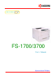
1.4. Setting Up and Interfacing 1—Open the Top Cover 1. Remove the packing tape from the printer. Top Cover 2. Open the printer top cover all the way. 2—Install the Toner Container 1. Take the toner container from the toner kit. 2. With the label side down, thoroughly shake the toner container (in the direction of the arrow) ten times or more to loosen and mix the toner inside. Toner Container 3. The bottom of the toner container is sealed with a sealing strip.
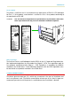
1.4. Setting Up and Interfacing Top Cover 5. When the toner container is installed correctly on the developer, push the top of the container unit ("PUSH HERE") until it locks in. * Make sure that the toner container is properly locked in the printer. 3—Close the Top Cover Close the top cover by pressing the arrowed part in this diagram. Top Cover 4—Install the Waste Toner Bottle The waste toner bottle is in the toner kit supplied with the printer.
1.4. Setting Up and Interfacing 2. Open the side cover on the left side of the printer. Side Cover 3. Insert the waste toner bottle with the bottle tilted slightly towards you as shown in the figure. Waste Toner Bottle 4. Ensuring that it is correctly inserted, close the side cover.
1.4. Setting Up and Interfacing 5—Add Paper *u u Before adding paper, remove the paper cassette all the way from the printer. Read the paper manufacturer’s instructions concerning handling of the paper. 1. Push the bottom plate until it locks. Bottom Plate 2. Set the paper in the cassette. The side of the paper that faces downward in the cassette is printed on. The paper size must match the cassette size. Tap the edges of the paper to align them neatly.
1.4. Setting Up and Interfacing 6—Open the Paper Stopper on the Face-down Output Tray Open the paper stopper as shown right. Paper Stopper 7—Install the Face-up Output Tray (if required) If you want the printed pages stacked face-up (in reverse order), mount the face-up output tray as follows. Depending on the size of the paper you use, mount the paper stopper on the face-up output tray as shown below.
1.4. Setting Up and Interfacing 8—Connect the Printer to the Computer The printer has two computer cable connectors and a slot for installing an option interface. The one marked " " is for a parallel (Centronics standard) interface. The one marked "I I I " is for a serial (RS-232C/RS-422A) interface. You may use whichever is convenient for your computer, with the option interface, if you have already have one installed. All interface connectors can be used simultaneously with different computers.
1.4. Setting Up and Interfacing 10—Print a Status Page Test that the printer works by printing out a status page as follows. 1. Switch on the printer’s power. The message display should indicate Self test. ☛ When the printer is first switched on after installation, there will be a delay of several minutes (approx. 6 to 7 minutes) before the printer gets ready to print. During this period, the message display shows Please wait. 2.
1.4. Setting Up and Interfacing The emulation mode can be changed from the printer control panel. To change the emulation mode, refer to the Mode Select Menu diagram on the last page of this manual. 13—Install the Printer Driver Printer drivers are provided for using the printer with Windows 3.1 or Windows 95. Use the Kyocera Digital Library CD-ROM supplied with the printer, or use the one supplied with Windows 3.1 or Windows 95.
1.4. Setting Up and Interfacing Windows 3.1 To install the printer driver for Windows 3.1, proceed as follows: 1. Insert the Kyocera Digital Library CD-ROM in your CD-ROM drive. 2. Start Windows on your computer. 3. Double click on Control Panel. 4. Double click on Printers . 5. Click on Add . 6. Click on Install . 7. Select Install Unlisted or Updated Printer under List of Printers. 8. Click Install . 9.
1.5. Multi-Purpose Tray Feeding 1.5. Multi-Purpose Tray Feeding The multi-purpose tray is incorporated in the front of the printer. It can be used in one of three modes: the cassette mode, manual mode or first mode. When used in the cassette mode, in combination with the main cassette, provides the printer with the capacity to accommodate 350 sheets of paper. The manual-feed mode enables printing on special paper, manually fed a single sheet at a time. Appendix B lists the paper types usable.
1.5. Multi-Purpose Tray Feeding 4. Check that the printer is Ready . 5. Press the FEED key until the message display indicates MP tray and the multi-purpose tray indicator on the printer symbol flashes, and Add paper appears on the message display. 6. Press the MODE key to display MP tray mode> . 7. Press the key to display >MP tray size , then by pressing the ENTER key, the size of the paper that will be fed from the multi-purpose tray will be set (see MODE SELECT MENU at the end of this manual).
1.5. Multi-Purpose Tray Feeding Manual mode 1. Press the MODE key to display MP tray mode > . 2. After pressing the ENTER key, the mode display is changed by pressing the + and - keys. Use these keys to display Manual and then press the ENTER key. MP tray mode Manual > 3. Press the EXIT key. 4. Place the paper on the multi-purpose tray inserting it as far as it will go. 5. Carefully lower the protector bar, and the paper will be correctly set in the multi -purpose tray. 6.
1.5. Multi-Purpose Tray Feeding Feeding Envelopes Envelopes should be fed face up, right side first, as shown below. From the MODE SELECT menu, set the printer to print in landscape page orientation. * To avoid trouble, we recommend that envelopes are delivered face-up. Use the STACK key on the printer control panel to select the face-up tray. Envelope Not all envelopes print well. See Appendix B for details on suitable types of envelopes. See page 2-3 for the envelope sizes that can be set.
1.6. Memory Card 1.6. Memory Card A memory card is a microchip card containing, for example, nonresident fonts and/or macros, forms, etc. The printer reads the contents of the card into its internal memory when power is switched on. The presence of this data in the printer memory can be confirmed on the status printout. ☛ The maximum card capacity that can be used is 16 Megabytes.
1.6. Memory Card Handling Memory Cards Memory cards contain sensitive electronic circuits. Treat them with appropriate care. p Memory cards are sensitive to electrostatic discharge. Please discharge yourself before touching a memory card. p Never attempt to force a memory card into its slot. p Never bend a memory card. p Avoid impact. Do not drop a memory card. p Do not touch the terminals of the memory card. p Do not spill water or other liquids on a memory card.
1.7. Memory Expansion Installation 1.7. Memory Expansion Installation In this section is explained how to expand the printer’s memory. Expanded printer memory enables you to print more complex pages, download more fonts, and define more macros. It begins by explaining how to remove the main circuit board from the printer, and explains how to install a SIMM (single in-line memory module) on the main circuit board.
1.7. Memory Expansion Installation * Withdrawing the Main Circuit Board from the Printer Be sure to remove the memory card first if inserted in the printer’s memory card slot. Withdraw the main circuit board completely from the printer as follows: 1. Turn the printer’s power off. Unplug the printer’s power cable and disconnect the printer from the host computer. 2. Remove the three screws from the printer’s rear cover. Power OFF ( ) 3.
1.7. Memory Expansion Installation SIMM to be used See your Kyocera dealer for purchasing information of the SIMMs that are best suited for use with this printer. Either 1 MB, 2 MB, 4 MB, 8 MB, 16 MB or 32 MB SIMMs can be used for memory expansion. Together with the memory already present in the printer, this allows memory to be expanded up to a total of 66 MB. The table below shows valid SIMM configurations for memory expansion.
1.7. Memory Expansion Installation Installing and Removing SIMMs Installing SIMMs Insert the SIMM into the socket as shown right. 1. 2. Insert the connector end of the SIMM into the socket. Carefully push the board upright until it snaps into place. Make sure that the catches at the ends of the socket fit into the holes at the ends of the SIMM board. Removing SIMMs To remove a SIMM, carefully pull the end catches slightly outwards and tilt the SIMM as shown, then pull the SIMM out of the socket.
1.7. Memory Expansion Installation Testing the Expansion Memory After you have finished installing SIMMs in the printer, test the printer to see if the installation has been successful. To test the expansion memory, proceed as follows: 1. Make sure the power switch is off. Plug the power cord into the printer and turn power on. 2. When the printer is on-line, press the STATUS key. 3.
2.1. Control Panel Chapter 2 Operating the Laser Printer This chapter explains the printer’s control panel and operating procedures. It covers the fundamental information you will need to use the page printer. 2.1. Control Panel The printer control panel comprises a message display, keys, and indicators, as shown below.
2.1. Control Panel Message Display The message display gives information in the form of short messages. The six messages listed below are displayed during normal warm-up and printing. Message Meaning Self test The printer is self-testing after power-up. Please wait The printer is warming up and is not ready. Ready The printer is ready to print. Processing The printer is receiving data, generating graphics, reading an memory card, or printing.
2.1. Control Panel Paper Size Indicator This is the paper SIZE indicator which indicates: p the size of the current paper cassette (letter size for the U.S.A. and A4 for European countries). The following abbreviations are used to indicate the paper sizes. A4 ISO A4 (21 cm ✕ 29.7 cm) BU Business (4-1/8 ✕ 9-1/2 inches)* A5 ISO A5 (14.8 cm ✕ 21 cm) DL ISO DL (11 ✕ 22 cm)* A6 ISO A6 (10.5 cm ✕ 14.8 cm)* C5 ISO C5 (16.2 ✕ 22.9 cm)* B5 JIS B5 (18.2 cm ✕ 25.6 cm) b5 ISO B5 (17.
2.1. Control Panel Symbolic Indicators The symbolic indicators light during normal operation and when the printer needs attention. Indicator Name Face-down stack indicator Flashing: Indicates the possibility that paper may be jammed at this point, open and remove any jammed paper. See Section 5.6. Lit: indicates when printed pages are delivered to the face-down output tray.
2.1. Control Panel Control Keys The control panel keys are used to configure the printer. ☛ Settings made with these keys effect only the interface currently in use. Key ON LINE CONT t STACK + FORM FEED Function Switches the printer on-line and off-line. 1. Depending on the message being indicated, there are cases where operation will continue after pressing the CONT key. If such a message is displayed, operation will be resumed after pressing this key. (See Table 5.3) 2.
2.2. Operating Procedures 2.2. Operating Procedures Switching Power On Check that the power cord is securely plugged in at both ends. Check that the printer is connected to the computer. In switching power on, the general rule is to switch on printer power first, computer power second. 1. Push the power switch to the ON ( | ) position. 2. Wait for the printer to warm up. During warm-up the message display indicates Self test.
2.2. Operating Procedures Feed Selection The FEED key selects the paper feed cassette [Cassette ] or multi -purpose tray [MP tray ] (or the option paper feeder[s], if installed) as the paper source. The FEED key can be used whenever the message display indicates Ready or Add paper. Press the FEED key. The selection cycles and is momentarily displayed in the message display as: Cassette MP tray The current selection is indicated by a green light on the printer symbol above the key.
2.2. Operating Procedures 1. Halt the printing program on the computer. The printer continues to print the data it has already received. It is a good idea to set the printer to off-line first. 2. Press the CANCEL key. The message display indicates Print Cancel ? and also the interface from which data is arriving, by the one of the following messages: Parallel Serial Option 3. * * Press the ENTER key. This clears the printing job on the interface indicated on the message display.
2.2.
2.2. Operating Procedures 1 — Firmware version information The printer’s firmware version number and release date. 2 — Current status information This information gives the printer’s temporary settings which are made by application or PRESCRIBE II commands or software. Note that this information pertains to the current interface only. Emulation type is indicated by the one of the following numbers.
2.2. Operating Procedures 5 — Memory allocation status Total memory shows the total amount of memory installed in the printer, including the expanded memory, if installed. User available shows how much memory is available for storing information to be printed. 6 — Service information This information is for service purposes. 7 — User defined font list The second status page is a list of fonts (if any) and font information that has been downloaded from the computer.
2.3. Using the Mode Select Menu 2.3. Using the Mode Select Menu This section explains how to use the MODE key on the control panel. The MODE key allows you to set or change the printer environment such as the number of copies to make, emulation, page orientation, code set, etc. to your specific needs. The following items can be selected by using the MODE , + and - , and ENTER keys. Also, the diagram on the last page in this manual gives a quick reference to the full options and the sequence of selection.
2.3. Using the Mode Select Menu Item MP tray mode Function > Default Setting Selects the multi-purpose tray mode from first, First cassette, or manual. The key allows access to submenu >MP A4 or Letter tray size , selects the size of multi-purpose tray. u Envelope size Selects the size of envelope for the optional envelope feeder. DL or Business Bulk feeder size Selects the size of paper for the optional bulk paper feeder.
2.4. Sleep (Ecopower) Mode 2.4. Sleep (Ecopower) Mode The printer has a sleep timer to conserve power when the printer is not printing, processing, or receiving data. You can adjust the timer value, the length of time the printer waits before entering sleeping mode in the absence of data. Any value from 0 to 120 [minutes] (the factory setting is 30 [minutes]) can be entered in 5 -minute increments. You can use the or key to move the cursor back and forth through the figures to rapidly set a large value.
2.5. KIR Level 2.5. KIR Level This printer incorporates the KIR (Kyocera Image Refinement) smoothing function. KIR provides high quality printing by providing a software-type improvement to the resolution. Three different types of KIR level can be selected. You can print a KIR test pattern to see how the current KIR setting works. To print a test pattern, follow Mode Select Menu on the last page of this manual. Q * The KIR setting is None . The KIR setting is Medium .
2.6. Ecoprint mode Optimized stripes The current KIR setting is optimal. Dark vertical stripes Set the KIR mode to Light or Medium . Try printing the test pattern again. If you still get dark vertical stripes, adjust the print density control to a lighter setting. (See the last page in this manual.) White vertical stripes Set the KIR mode to Medium or Dark . Try printing the test pattern again. If you still get white vertical stripes, adjust the print density control to a darker setting.
2.7. Resource Protection 2.7. Resource Protection When you switch from the HP LaserJet emulation to another, all downloaded fonts and macros are lost. Resource protection preserves these PCL resources in memory so that they are intact when you change the emulation back to HP LaserJet 4 Plus. By using the printer’s MODE SELECT, you can select from two resource protection modes as follows: >Resource prot. Permanent In this mode, the printer stores fonts, macros, symbol sets, etc.
2.9. Setting the Audio Warning (Buzzer) 2.9. Setting the Audio Warning (Buzzer) In addition to the message displayed when the paper supply is exhausted, or when paper jamming occurs, an audio warning is made to sound. This is useful, for example, when the printer is in a location some distance from the user. The audio alarm is set to ON when leaving the factory. An audio alarm corresponding to the type of printer error will sound according to the table below.
2.9. Setting the Audio Warning (Buzzer) The alarm will continue to sound while the error condition continues (if the printer is in the sleep mode, the alarm will be silent for that period alone). The alarm will cease to sound, however, when the CANCEL key is pressed. To rectify the various error conditions listed above, please refer to Chapter 5 of this manual, or to the operating manuals accompanying the various optional equipment.
2.10. Operating a Memory Card 2.10. Operating a Memory Card Hints on Writing Fonts to the Memory Card Some memory card writer utility programs are available for writing data to the memory card. If you write fonts into a memory card, we recommend you write them as font data and not as host data. Fonts written in a memory card as font data are automatically loaded in the printer when it is switched on and are usable on all the printer interfaces simultaneously.
2.10. Operating a Memory Card Writing Data to a Memory Card A memory card can hold up to 127 data partition names, depending on its capacity. When writing to the card, a name is assigned automatically. You can use the procedure later in this section to print a list of data names for confirmation. * You cannot write font data to a memory card with the printer. To write data to a memory card, proceed as follows.
2.10. Operating a Memory Card 4. u Check that the message display has changed to Waiting , then press the (FORM FEED ) key. This writes the file to the memory card and instructs the printer to automatically print out a memory card write information page as shown below. Type of data written (currently only type 2 is supported). Partition (data) name. The destination name of data written to the card. Write data length. The size of the written data on the memory card in bytes. Others. Error information.
2.10. Operating a Memory Card Formatting a Memory Card Formatting allows data to be written to the card. A new memory card must be formatted before it can be used in the printer. * Formatting destroys any existing data on the memory card. First check that the memory card is writable (for example that the memory card is not write -protected, and its internal battery is not exhausted).
2.10. Operating a Memory Card Printing a list of data names The printer prints a list of all data names (referred to as partitions) stored in a memory card for reference. (Printing a list is also available for a font card.) The printout (example above) includes the following information. Partition (data) number. Reference number for each written data. Name. The destination name of the written data as assigned automatically by the printer. Size. The size of the written data in bytes. Type.
3.1. Bitmap and Scalable Fonts Chapter 3 Fonts This chapter describes the types of fonts you can use with the printer, including the printer’s resident and KPDL fonts (option), and symbol sets. 3.1. Bitmap and Scalable Fonts A font is a set of characters of a particular design. The design is referred to as a typeface. Several characteristics identify a font. These include the font type (bit map or scalable), symbol set, spacing, pitch, height, style, stroke weight, and typeface family.
3.1. Bitmap and Scalable Fonts Bitmap fonts A bitmap font is made of a fixed bit pattern (Figure 3.1.). This pattern is stored in a special format for use in the printer. Bitmap fonts have a fixed height (size) for each character. Therefore, different font sets are required for different font sizes. For example, Dutch801BM10-Roman is a 10 -point font and Dutch801BM8-Roman is an 8-point font. Figure 3.1. Bitmap Font Character Scalable fonts Scalable fonts provide the outline of the characters (Figure 3.2.
3.2. List of Fonts 3.2. List of Fonts This section contains a full list of the printer’s resident fonts. You can print the same font list from the printer by using the printer’s control panel key. To print a list of fonts, refer to Mode Select Menu , List of Resident fonts. Bitmap Fonts The printer has 79 resident bitmap fonts. Note that all resident bitmap fonts include the letters BM in the typeface name. Scalable Fonts The printer has 45 resident scalable fonts.
3.2.
3.2.
3.2.
3.2.
3.2.
3.2.
3.2.
3.3. Symbol set 3.3. Symbol set A symbol set is the set of alphabetical and numerical characters and symbols the printer prints. Each character is assigned to a particular character code. The page printer offers not only a large selection of bitmap and scalable fonts but also a large selection of symbol sets (also referred to as character sets). This is because the printers the Kyocera page printer emulates have a number of their own symbol sets for printing in different languages and other purposes.
3.3. Symbol set Table 3.2. Scalable Fonts Symbol sets SSET value 4 9 14 19 21 37 38 39 53 78 83 173 174 180 202 205 234 269 277 293 308 309 330 341 373 394 405 426 458 501 565 629 SSET ID 0D 0I 0N 0S 0U 1E 1F 1G 1U 2N 2S 5M 5N 5T 6J 6M 7J 8M 8U 9E 9T 9U 10J 10U 11U 12J 12U 13J 14J 15U 17U 19U Symbol set ISO 60: Norway ISO 15: Italian ECMA-94 Latin 1 ISO 11: Swedish ISO 6: ASCII ISO 4: U.K.
3.3.
4.1. Toner Kit Replacement Chapter 4 Maintenance This printer is designed to provide years of trouble-free service without the necessity of printer module replacement. However, you must replace the toner container in the printer with a replacement container from a new toner kit. Also, to ensure good print quality, various parts inside the printer must be cleaned at regular intervals. 4.1.
4.1. Toner Kit Replacement Supplying Toner ☛ Before proceeding, take note of the following: u u u Do not leave floppy disks etc. lying around while performing this maintenance procedure. This procedure tends to raise a little toner dust which can harm magnetic recording media. Do not attempt to reuse the waste toner remaining in the toner container. Use only the toner kit exclusively designed for the printer.
4.1. Toner Kit Replacement 5. The bottom of the toner container is sealed with a plastic strip. Carefully pull the sealing strip off the toner container, making sure not to leak any toner. Dispose of the sealing strip. 6. Install the toner container on the developer as shown in the diagram. ☛ Be sure to peel off the seal on the toner container before mounting the toner container on the developer unit. 7. When the toner container is installed correctly on the developer. 8.
4.1. Toner Kit Replacement Replace the Waste Toner Bottle ☛ When replacing the toner container, the used waste toner bottle in the printer should also be replaced with a new one from the new toner kit. 1. Open the printer side cover. Side Cover Old Waste Toner Bottle 2. Remove the waste toner bottle as shown right. ☛ Remove the waste toner bottle as gently as possible so as not to scatter the waste toner inside. Do not let the opening of the waste toner bottle face downward. 3.
4.1. Toner Kit Replacement 5. Locate the new waste toner bottle in the toner kit, and install in the printer as shown right. ☛ Do not cap the new waste toner bottle. Insert the new waste toner bottle with the bottle tilted slightly towards you as shown in the figure. New Waste Toner Bottle 6. After ensuring that the bottle is correctly installed, close the side cover.
4.2. Cleaning 4.2. Cleaning In addition to the maintenance procedures described on the following pages, the charger wire in the drum unit and paper feed unit should be cleaned from time to time, or whenever print quality problems occur. To avoid print quality problems, the following printer parts must be cleaned with every toner container replacement. ☛ If the toner container has been replaced when the message Replace Toner Clean printer was displayed, the message Clean printer ..
4.2. Cleaning Cleaning the Grid 1. ☛ 2. Take the grid cleaner from protective bag in the new toner kit, and remove the cap. Cap Protective Bag The grid cleaner pad is impregnated with water. Perform the following cleaning procedure before the pad dries. Grid Cleaner Attach the grid cleaner to the printer with the pad uppermost, as shown in the diagram. Grid Cleaner 3.
4.2. Cleaning Paper Feed Unit To avoid print quality problems due to paper dust and debris, clean the paper feed unit in the following manner. 1. Pull the paper feed unit release lever up and draw the paper feed unit all the way out until it stops. 2. Paper Feed Unit Release Lever Wipe the paper dust on the registration roller and the paper ramp using the wiper cloth included in the toner kit.
5.1. General Guide Chapter 5 Troubleshooting This chapter explains how to handle printer problems which may or may not occur. The procedures are easy to follow. If a problem persists after you have completed the appropriate troubleshooting procedures, call for the assistance of a service person. 5.1. General Guide If the printer does not print If nothing is displayed on the message display on the front control panel, then you probably have a power problem. See section 5.2 .
5.2. Power Problems 5.2. Power Problems * The printer power rating must be within the voltage range in your country. If in doubt, consult your dealer. If nothing happens when you switch the printer’s power on, you have a power problem. The symptoms are a dark control panel, no printing, and no fan sound. Proceed as follows. Check the power switch. The on position is marked "| ". The off position is marked " " Check the power cord.
5.4. Print Quality Problems 5.4. Print Quality Problems Print quality problems range from uneven tone to completely blank output. The troubleshooting procedure for each type of problem is given below. If the checks explained in this section do not solve the problem, call for the assistance of a service person. Completely blank printout Check the developer unit.
5.4. Print Quality Problems Dropouts, horizontal streaks, stray dots Clean the charger wire. Open the printer side cover. Pull the green main charger wire cleaning knob slowly in and out a few times. See Section 4.2. Note the spacing of the defects. If the defects occur at regular intervals of 60.6 mm (2.4 inches), the problem may be a dirty transfer roller. Call for the assistance of a service person. If the defects occur at regular intervals of 94 mm (3.
5.4. Print Quality Problems Faint or blurred printing Check the control panel. If the Toner low TK-20 Clean printer message is displayed and the cator is flashing, install a new toner kit. See Section 4.1. indi- Set the print density from the control panel to a higher level than the current setting. See Section 2.8. Set the control panel Paper type setting to Thick . Check the Ecoprint setting. See Section 2.6. Grey background Check the control panel.
5.4. Print Quality Problems Dirt on the top edge or back of the paper Check the paper chute and the ramp. Draw out the paper feed unit and check for toner on the paper ramp. Clean the paper ramp (see Section 4.2. ) using the wiper supplied, or a soft, dry, lint-free cloth. Check the transfer roller. If the transfer roller is dirty with toner, try printing several pages; or call for the assistance of a service person. Characters out of position Check the file or program.
5.5. Indicators and Messages 5.5. Indicators and Messages The tables on the following pages indicate how to respond to problems indicated by the control panel symbolic indicators and messages. Indicators Table 5.1 Symbolic Indicators Indicator Condition Flashing Lit Fast Flashing Slow Flashing Lit Flashing ATTENTION Lit Corrective Action The printer has run low on toner. The toner should be replaced as soon as possible. Install a new toner kit. See Section 4.1. (Toner Empty) There is a paper jam.
5.5. Indicators and Messages Maintenance Messages Table 5.2 Maintenance Messages Message Top cover Open Side cover Open Paper feed unit Open Face-down tray paper full Corrective Action Open the top cover, then close tightly. Open the side cover, then close tightly. Open the paper feed unit, then close tightly. Add paper The face-down tray has become full (approx. 250 pages). You must remove all printed pages from the face-down tray.
5.5. Indicators and Messages Message Call service person En:123456 Call service person Fn:123456 Corrective Action Mechanical error (n =0 , 1 , 2 , ...)—Call a service person. The printer does not operate when a message beginning with E is displayed. The total number of pages printed is also indicated. Controller error (n =0 , 1 , 2 , ...)—Call a service person. The printer does not operate when a message beginning with F is displayed. The total number of pages printed is also indicated.
5.5. Indicators and Messages Message MEMORYCARD err ## .. Press CONT >Read fonts Failed I/F occupied Processing PAR FIT A4 Processing PAR 600 A4 Processing PAR 300 A4 5-10 Corrective Action This message appears when an error occurs during access to the memory card using the PRESCRIBE II ICCD command or from the printer’s control panel (codes 09 and 11 only). The error is indicated by one of the numbers ## listed below.
5.6. Correcting a Paper Jam 5.6. Correcting a Paper Jam The Paper jam message is displayed on the message display when paper becomes stuck in the paper transport system, the paper feed timing is incorrect, or paper fails to feed at all. The jam can be corrected by removing the paper. The printer goes off-line when the Paper jam message is displayed. Compare the symbol on the front panel that is flashing to Figure 5.1 and take the appropriate action listed below: Check the facedown output tray.
5.6. Correcting a Paper Jam * When pulling the paper, pull it gently so as not to tear it. Torn pieces of paper are difficult to remove and may be easily overlooked, deterring the jam recovery. Rear Cover Figure 5.2. Rear Cover Paper Feed Unit Figure 5.3. Paper Cassette Figure 5.4.
Simbol Set Tables Chapter 6 Symbol Set Tables The following tables show all the characters included in the most common symbol sets available with the five emulations.
6.1. IBM Symbol Sets 6.1.
6.1.
6.1.
6.1.
6.1.
6.1.
6.2. Diablo 630 Symbol Sets 6.2.
6.2.
6.2.
6.3. LQ-850 Symbol Sets 6.3.
6.3.
6.4. HP LaserJet 4 Plus Symbol Sets 6.4.
6.4.
6.4.
6.4. HP LaserJet 4 Plus Symbol Sets LaserJet 4 Plus PC-8 (10U) To have the printer print the characters of decimal numbers of 7 through 15, and 27, set the printer to the HP PCL transparent mode (ESC&p#X).
6.4. HP LaserJet 4 Plus Symbol Sets LaserJet 4 Plus PC-8 (D/N) (11U) To have the printer print the characters of decimal numbers of 7 through 15, and 27, set the printer to the HP PCL transparent mode (ESC&p#X).
6.4. HP LaserJet 4 Plus Symbol Sets LaserJet 4 Plus PC-850 (12U) To have the printer print the characters of decimal numbers of 7 through 15, and 27, set the printer to the HP PCL transparent mode (ESC&p#X).
6.4.
6.4.
6.4.
6.4.
6.4.
6.4.
6.4.
6.4.
6.4.
6.4.
6.4.
6.4.
6.4.
6.4.
6.4.
6.4.
6.4.
6.4.
6.4.
Printer Specifications Appendix A Printer Specifications Description Item FS-1700 FS-3700 Printing method Electrophotography, laser scan. Printing speed 12 pages/minute (A4 or letter-size paper, when printing multiple copies of the same page) Resolution 600 dots/inch (vertical and horizontal) with KIR (Kyocera Image Refinement) First print Approx. 15 seconds (A4 or letter size), depends on input data. Approx. 12 seconds (A4 or letter size), depends on input data. Warm-up time Approx.
Printer Specifications Item Description FS-1700 FS-3700 Capacity of output trays Face-down tray—250 sheets of thickness 0.1 mm. Face-up tray—250 sheets of thickness 0.1 mm. Ambient conditions Temperature: 10°C to 32.5°C (50°F to 90.5°F) Humidity: 20% to 80% RH Optimum conditions: 20°C (68°F), 65% RH. Altitude: Max. 2000m (6500 feet) Illumination: Max. 1500 lux Power requirements 120 V, 60 Hz, max. 5.8 A (U.S.A./Canada) 220—240 V, 50Hz, max. 3 A (European countries) Max.
B.1. General Guidelines Appendix B Paper Selection B.1. General Guidelines The printer is designed to print on high-quality copier bond paper (the kind used in ordinary dry copier machines), but it can accept a variety of other types of paper as well within the limits specified below. * The manufacturer assumes no liability for problems that occur when paper not satisfying these requirements is used. Selection of the right paper is important.
B.2. Selecting the Right Paper Paper Specifications The following table summarizes the basic paper specifications. Details are given on the following pages. Table B.1 Specifications Item Weight Thickness Dimensional accuracy Squareness of corners Moisture content Direction of grain Pulp content Specification 60 to 90 g/m2 (16 to 24 lbs./ream) 0.086 to 0.110 mm (3.4 to 4.3 mils) ± 0.7 mm (± 0.0276 inches) 90° ± 0.2° 4% to 6% Long grain 80% or more B.2.
B.2. Selecting the Right Paper Paper Size Cassettes and a multi-purpose tray are available for the paper sizes listed in Table B.2 . The dimensional tolerances are ± 0.7 mm (±0.0276 inches) for the length and width. The angle at the corners must be 90° ± 0.2°. Table B.2 Paper Sizes for Paper Feeding Multi-Purpose tray Monarch Business International DL International C5 International B5 Executive Commercial 9 Commercial 6-3/4 ISO A6 JIS B6 Size 3-7/8 x 7-1/2 inches 4-1/8 x 9-1/2 inches 11 x 22 cm 16.
B.2. Selecting the Right Paper The moisture content of the paper varies with the relative humidity in the room. When the relative humidity is high and the paper absorbs moisture, the paper edges expand, becoming wavy in appearance. When the relative humidity is low and the paper loses moisture, the edges shrink and tighten, and print contrast may suffer. Wavy or tight edges can cause misfeeding and alignment anomalies. The moisture content of the paper should be 4% to 6%.
B.3. Special Paper Packaging: Paper should be packed in a sturdy carton to protect it from damage during transport. Quality paper obtained from a reputable supplier is usually properly packaged. B.3. Special Paper The following types of special paper can be used: p Overhead projection (OHP) film p Adhesive-backed label paper p Envelopes p Colored paper p Preprinted paper p Recycled paper Use paper that is sold specifically for use with copiers (heat-fusing type).
B.3. Special Paper Adhesive-Backed Labels The basic rule for printing on adhesive labels is that the adhesive must never come into contact with any part of the printer. Adhesive paper sticking to the drum or rollers will damage the printer. Label paper must be manually fed. Label paper has a structure comprising three layers, as shown in Figure B.1 . The top sheet is printed on. The adhesive layer consists of pressure-sensitive adhesives.
B.3. Special Paper Envelopes The printer can print on envelopes using paper with a basis weight of 60 to 79 g/m2 (16 to 21 lbs/ream). Envelopes must be manually fed. An envelope is a more complex object than a single sheet of paper. For this reason, it may not be possible to obtain consistent printing quality over the entire envelope surface. Many envelopes have a diagonal grain orientation. (See Paper Grain above.) This orientation is more likely to wrinkle and crease on its way through the printer.
C.1. Parallel Interface Appendix C Host Computer Interface This appendix describes the signals used in the laser printer’s parallel, RS-232C/RS-422A interfaces. It also lists pin assignments, signal functions, timings, connector specifications, and voltage levels. The RS-232C/RS-422A protocols are also covered. Finally, it explains the use of the printer in a multi-computer environment. C.1.
C.1. Parallel Interface Interface Signals The pins of the parallel interface connector carry the signals listed in Table C.1 . Asterisks in the table indicate signals that are active low. The table also indicates whether each signal is incoming or outgoing with respect to the printer. Table C.1.
C.1. Parallel Interface Detailed descriptions of the signals follow. Strobe* [nStrobe] (Pin 1) A negative-going Strobe* pulse causes the printer to read and latch the data on the Data 0 [1] to Data 7 [8] signal lines. Data 0 [1] to Data 7 [8] (Pins 2 to 9) These eight signals form the data byte sent from the host computer to the printer. Data 7 [8] is the most significant bit. Acknowledge* [nAck] (Pin 10) This negative-going pulse acknowledges the previous character received by the printer.
C.1. Parallel Interface Select In [NSelectIn] (Pin 36) This signal is used in some versions of the Centronics interface to enable the computer to force the printer on-line. In high-speed mode, it is used as an interrupt.
C.2. RS-232C/RS-422A Interface C.2. RS-232C/RS-422A Interface RS-232C interface Interface Signals The pins of the printer’s RS-232C interface connector carry the signals listed in Table C.2 . The table also indicates whether each signal is incoming or outgoing with respect to the printer. Table C.2.
C.2. RS-232C/RS-422A Interface RS-232C Interface Voltage Levels The voltage levels of the interface signals conform to EIA RS-232C specifications. SPACE is from 3 volts to 15 volts. MARK is from -3 volts to -15 volts. Voltages between -3 volts and 3 volts are undefined. RS-422A interface The serial interface of this printer was set to RS-232C mode before leaving the factory. However, by changing the jumper connector on the main circuit board, the interface can be changed to RS-422A mode.
C.2. RS-232C/RS-422A Interface * Withdrawing the Main Circuit Board from the Printer Be sure to remove the memory card first if inserted in the printer’s memory card slot. Withdraw the main circuit board completely from the printer as follows: 1. Turn the printer’s power off. Unplug the printer’s power cable and disconnect the printer from the host computer. 2. Remove the three screws from the printer’s rear cover. Power OFF ( ) 3. * Pull the main circuit board all the way out of the printer.
C.2. RS-232C/RS-422A Interface Verifying the Setting The procedure described below should be followed to verify that the RS-422A mode had been correctly set. 1. Make sure the power switch is off. Plug the power cord into the printer and turn power on. 2. When the printer is on-line, press the STATUS key. 3. If the mode has been correctly set, "RS-422A " should be indicated on the status page printout. Please refer to the sample printout shown below.
C.2. RS-232C/RS-422A Interface RS-422A interface voltage levels The interface signal voltage levels conform with the EIA RS-422A standard. The differential voltage varies from 200 mV to 6V. SERIAL Connector The connector marked "I I I " (RS-232C/RS-422A) on the rear panel is a DB-25S connector. Use a DB-25P connector (or equivalent) for the connector on the cable.
C.3. RS-232C/RS-422A Protocol C.3. RS-232C/RS-422A Protocol A protocol is a set of rules the computer follows in sending data to the printer. The RS-232C/ RS-422A parameters are stored in battery backed-up memory. They are indicated on the status printout. They can be changed by the FRPO (firmware reprogram) command described in the Programming Manual. The parameters and their identification codes are given below.
C.3. RS-232C/RS-422A Protocol H5: Protocol logic Parameter value 0 1 2 3 4 5 Meaning Combination of 1 and 3 below DTR/DSR, positive logic DTR/DSR, negative logic XON/XOFF ETX/ACK XON/XOFF recognized only as protocol The factory setting is 0. H6: Buffer nearly-full threshold This is a percentage from 0 to 99. The factory setting is 90. H7: Buffer nearly-empty threshold This is a percentage from 0 to 99. The factory setting is 70.
C.4. RS-232C Cable Connection C.4. RS-232C Cable Connection Preparing an RS-232C Cable After obtaining an RS-232C cable, check that it is wired correctly, referring to the pin assignment table in Appendix C. If you have an IBM communication adapter cable type 1502067, you will have to resolder the wiring at the printer end of the cable. The procedure is as follows. 1. Unscrew the plastic cover from the printer end of the cable. 2. Next to each of the wires inside the cable is a bare shield wire.
C.4. RS-232C Cable Connection Baud rate=9600 bps, Data bits (character length)=8 bits, Stop bits=1, Parity=None The three RS-232C protocols are XON/XOFF and DTR. The printer performs all three of them simultaneously, using positive logic for DTR. If you are uncertain as to the printer’s current parameter settings, you can reset them to the values listed above by following the manner described in the last page in this manual. 8. Set the computer to the same parameters as the printer.
Index Index A Abandoning a printing job 2-7 Adhesive label B-6 Amorphous silicon drum ix AppleTalk interface kit (IB-3) 1-15 Auto cassette 2-13 Automatic manual feeding 1-20 B Bit pattern 3-2 Bitmap font naming format 3-2 Bitmap fonts 3-2, 3-3 Buzzer (Audio warning) 2-18 C Cassette size B-3 Centronics 1-13 Cleaning grid cleaner 4-1, 4-7 main charger unit 4-6 paper feed unit 4-8 Code set 2-12 Code sets Last page Contents of carton 1-4 Control keys - key 2-5 + key 2-5 CANCEL key 2-5 CONT key 2-5 ENTER key
Index M N Macintosh computer AppleTalk interface kit (IB-3) 1-15 PostScript upgrade kit 1-15 Main circuit board 1-23, C-6 Maintenance messages Add paper 5-8 Call service person En 5-9 Call service person Fn 5-9 Clean printer ..
Index SIMM installing 1-26 removing 1-26 sockets 1-24 test 1-27 Simple Network Management Protocol (SNMP) x Sleep mode x, 2-14 Please wait 2-14 Sleeping 2-14 Sleep timer 2-14 Soft fonts 3-1 Stack selection 2-6 Status page 1-14 printing 2-8, 5-1 Symbol sets 3-11, 6-1 Diablo 630 symbol sets 6-8 HP LaserJet 4 Plus symbol sets 6-13 IBM symbol sets 6-2 LQ-850 symbol sets 6-11 U User’s Manual xii W Waiting 2-2 Waste toner bottle Windows 1-15 Wiper cloth 4-8 1-9 T Temperature and humidity 1-2 Thick paper 2-1
Mode Select Menu Sub Items This diagram gives quick reference to the full menu options and the sequence of selection. Vertical movement between delections in the diagram is achieved by the + and keys; and horizontal movement by the and keys.
*1: Depending on the emulation selected, the following code sets are available. HP LaserJet 4 Plus ISO 6: ASCII ISO 11: Sweden ISO 15: Italian ISO 17: Spain ISO 21: Germany ISO 60: Norway ISO 69: France HP Roman-8 ECMA-94 Latin 1 US Legal IBM PC-8 IBM PC-8 (D/N) IBM PC-850 ISO 4: U.K. IBM Proprinter X24E or Line Printer DIABLO 630 Bitmap and Scalable Fonts DIABLO US IBM US DIABLO France IBM D/N DIABLO Germany IBM PC-850 DIABLO U.K.