Troll Systems Corporation Ground-Based Products VanLink System Installation Guide Troll Systems Corporation Technical Publications Document VLSG-01 Revision – 0 10/17/2008 www.trollsystems.
NOTICE The information in this document incorporates proprietary rights of Troll Systems Corporation 24950 Anza Avenue Valencia, CA 91355, U.S.A. Any party accepting this document acknowledges that it contains proprietary confidential information and agrees that it shall not be duplicated in whole or in part, nor disclosed to others without the written consent of Troll Systems Corporation.
VANLINK SYSTEM GUIDE Table of Contents Summary ...................................................................................................................................1 VanLink Equipment Components .............................................................................................1 Required Hardware ............................................................................................................... P-1 Software Requirements ...................................................
Master Controller Software Requirements ..................................................................... 1-4 Introduction ..................................................................................................................... 2-1 Safety Recommendations ............................................................................................... 2-1 Installation Requirements ...............................................................................................
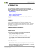
VANLINK SYSTEM GUIDE INTRODUCTION This Installation Guide is intended for use with the VanLink System featuring TouchStar™ Technology designed and fabricated by Troll Systems Corporation. The sections and appendices that make up this manual are as follows: Safety Considerations Section 1 - Vanlink System Overview Section 2 - VanLink System Requirements Section 3 - Engineering Drawings This guide or manual is based on the latest information available at the time of publication.
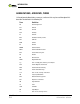
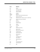
INTRODUCTION ABBREVIATIONS, ACRONYMS, TERMS Listing of general abbreviations, acronyms, and terms that may be used throughout this document are defined in the following list.
ABBREVIATIONS, ACRONYMS, TERMS Term Definition LAT Latitude LCD Liquid Crystal Display LED Light Emitting Diode LNA Low-Noise Amplifier LNG Longitude MICOWV Microwave NEMA National Electrical Manufacturing Association NIC Network Interface Card nm (NM) Nautical Mile (note: 1 nautical mile equals 1.
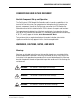
INTRODUCTION PACKAGING Use the original packaging material used for your TNS3000 network Server if available and in good condition. If you must return your product to Troll Systems Corporation for repair (and you no longer have your original box and packing materials), Troll will send you a packing box specifically designed to ship the product without damage.
CONVENTIONS USED IN THIS DOCUMENT CONVENTIONS USED IN THIS DOCUMENT VanLink Component Set-up and Operation The Troll Systems V750 Remote Site Controller and its innovative capabilities is the heart of the VanLink system. For comprehensive information for this complex and dynamic component, consult the Troll Systems manual for the S750 Remote Site Controller manual which is identical to the V750 in almost all respects and functions.
INTRODUCTION WARNING: This format is used for warnings which include the risk of fire. Cautions Cautions are included to alert the user that damage to the equipment is possible if the instructions in the operational or procedural task are not followed precisely. Cautions describe the hazards and possible impact that could occur if the cautions are not observed. CAUTION: This format is used for all cautions.
CONTACT INFORMATION CONTACT INFORMATION Troll Systems Corporation is committed to providing its customers with quick and friendly service. If you have questions regarding your Troll product, or if you experiencing a technical problem, please contact us at: Troll Systems 24950 Anza Drive Valencia, CA 91355 Phone: (661) 702-8900 Fax: (661) 702-8901 Alternatively, you can contact us via e-mail at: Sales sales@trollsystems.com Service service@trollsystems.
INTRODUCTION NOTES User Manual P-8 VanLink System featuring TouchStar™ Technology - Troll Systems Corporation Document VLSG-01 - 10/17/2008
VANLINK SYSTEM GUIDE SAFETY CONSIDERATIONS GENERAL SAFETY PRECAUTIONS The following general safety precautions are not related to any specific procedures and therefore do not appear elsewhere in this publication. They are, however, precautions that personnel need to understand and apply when operating or repairing equipment. Installation, operation, and maintenance should be performed only by qualified personnel.
VanLink Safety Considerations For safety reasons Troll Systems does not offer control of masts. There are, however, methods for implementing safety measures to prevent any damage to the antenna or surrounding equipment by monitoring the mast’s position and locking out control when the mast is down.
Be Familiar With Resuscitation Techniques Personnel working with or near high voltages should be familiar with modern methods of resuscitation. It is beneficial to ensure that personnel are capable of performing Cardio-pulmonary resuscitation (CPR) should the need arise. Coincidental Damage to Equipment in Cabinets CAUTION: Pushing or forcing equipment into/out of equipment cabinets and enclosures can easily damage surrounding equipment, cables/wiring, or fiber optic cable installations.
Electrostatic Discharge Sensitive (ESDS) Components CAUTION: Beware of electrostatic buildup. Delicate solid-state Integrated Circuits (ICs) can be damaged by improper handling procedures. Use proper electrostatic safeguards when installing/removing circuit cards and handling ESD sensitive assemblies. As required, wear a grounded wrist strap, use antistatic floor and table mats, and minimize the handling of sensitive solid-state devices.
Minimize Handling. Keep parts in original containers until ready for use. Discharge personal static before handling devices. Handle devices by the body. Use anti-static containers for handling and transport. Do not slide devices over any surface. Avoid plastic, vinyl and styrofoam in work area. When removing plug-in assemblies, handle only by non-conductive edges and never touch open edge connector except at static-free work station.
NOTES User Manual S-6 VanLink System featuring TouchStar™ Technology - Troll Systems Corporation Document VLSG-01 - 10/17/2008
VANLINK SYSTEM GUIDE SECTION 1 VANLINK SYSTEM OVERVIEW 1.1 SYSTEM OVERVIEW The Troll Systems VanLink remote broadcast van control interface is a comprehensive and dynamic system designed to be integrated into vehicles utilized in Electronic News Gathering functions in the field. Refer to Figure 1–1 through Figure 1–3.
SYSTEM OVERVIEW 1.1.
SYSTEM OVERVIEW 1.1.1.1 Remote Control from the Studio or Control Center Comprehensive remote control of ancillary vehicle functions including pan and tilt, vehicle tracking and signal optimization. (see Figure 1–3). Troll Systems MC17 Master Controller with GUI Page / Map PC Switcher / Router WAN Figure 1–3.
SPECIFICATIONS 1.2 SPECIFICATIONS 1.2.1 Required System Components 1.2.1.
VANLINK SYSTEM GUIDE SECTION 2 VANLINK SYSTEM REQUIREMENTS 2.1 INTRODUCTION This section provides information detailing the system requirements and theory of operation of the Vanlink Control System. The following topics are discussed: 2.2 • Safety Recommendations • System Requirements • Theory of operation and recommendations SAFETY RECOMMENDATIONS Equipment installation and operation should only be performed by qualified personnel that are familiar with the type of equipment being installed.
INSTALLATION REQUIREMENTS 2.3 INSTALLATION REQUIREMENTS The Vanlink System components install easily in a standard 19-inch equipment rack. Physical characteristics of the Vanlink System components are provided in the applicable assembly drawings. Both standard and custom rack installations must meet these dimensional requirements in order to properly accommodate the installation of the controller. 2.3.1 Power Requirements Power provided at the vehicle must meet either of the following requirements: 2.
INSTALLATION REQUIREMENTS 2.3.3.1 Running Cables Cables should only be installed by qualified personnel who are familiar with the electrical requirements and safety precautions that are necessary to properly and safely install (run) these items. The cables should be inspected prior to installation. Connectors should be visually inspected prior to connecting to their mating connector. 2.3.3.
INSTALLATION REQUIREMENTS 2.3.3.3 Pan and Tilt Cabling and Connector Requirements The pan and tilt cable and connector requirements are as follows (refer to Figure 2–2): • The pan/tilt controller is connected directly to the QPT pedestal on the roof via a terminal strip in the rear of the controller. — An additional four (4) wires are required for azimuth/elevation feedback.
INSTALLATION REQUIREMENTS 2.3.3.4 GPS/IMU Connectivity • Cabling consisting of six (6) wires will need to run from the V750 to the GPS/IMU. — It is possible to use existing wires to avoid running new wires by creating an extension with a DB9 connector on each end of the wires. Otherwise the cable from the GPS/IMU will be run from the roof down to the V750 where it will connect to the harness. • 2.3.3.5 2.3.
INSTALLATION REQUIREMENTS NOTE: Port 80 is not required if the EVDO/3G router utilizes a static IP address Troll Systems TNS3000 Network Server Studio Network Router Figure 2–3.
GPS/IMU ASSEMBLY 2.3.5 Typical Network Configuration for VanLink 2.3.5.1 GPS/IMU Mounting Considerations In order for the GPS/IMU to continually provide accurate heading information a few considerations need to be made when mounting the assembly on the roof of the vehicle. • The GPS/IMU assembly must be mounted as far away from any significant sources of current such as flood lights or motors as possible because it is sensitive to EMI generated by these types of devices.
GPS/IMU ASSEMBLY Figure 2–4. GPS/IMU Assembly 2.4.2 VanLink GPS One of the key functional features of VanLink is its ability to utilize the vehicles current location (Latitude/Longitude), its orientation (Reference to magnetic North), and the static coordinates of each receive site in order to point the dish to the appropriate azimuth. For this feature to be operational, Troll Systems will require a list of each receive site and its coordinates (preferably in DD:MM.
CALIBRATION 2.5 CALIBRATION There are two components of VanLink requiring calibration that need to be performed prior to successful operation of the VanLink operational system. The first component to be calibrated is the magnetometer. The second component to be calibrated is the antenna. 2.5.1 Magnetometer Calibration After installation, the magnetometer (part of the GPS/IMU assembly) needs to be calibrated.
OPERATING REQUIREMENTS 2.7 OPERATING REQUIREMENTS In order for VanLink to be effective there has to be GPS coverage and a clear microwave path for ENG operations from where the vehicle is located. For remote control of VanLink, the vehicle will also need to be in an area that has the coverage from the customer’s particular cellular service provider. 2.7.1 Transmitter Control / Available Options There are Control-PACs already written for most transmitters in use for ENG.
VANLINK SYSTEM GUIDE SECTION 3 ENGINEERING DRAWINGS 3.