
Instruction Manual


85
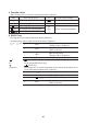
4.3.3 DC+AC Voltage Measurement ( + )
1) Turn the function switch to the “
V ” position.
2)PresstheSELECTkeytoselectDC+ACvoltagemeasurement.
(The display shows the “ + ” symbol.)
3)Plugthetestleadsintotheinputterminals.
4) Connect the test leads to the circuit under test and then read the value
when it stabilizes.
Test leads
RedBlack
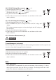
4.3.4 DC, AC Voltage Dual Display ( • )
1) Turn the function switch to the “DCV” position.
2) Press the SELECT key twice to change the mode to DC/AC voltage dual
display.
DC voltage measurement appears on the main display and AC voltage on
the sub-display.
3)Plugthetestleadsintotheinputterminals.
4) Connect the test leads to the circuit under test and then read the value
when it stabilizes.
Test leads
RedBlack
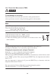
4.3.5 ResistanceMeasurement(Ω)
CAUTION
To avoid damage to instrument
Turn off the power to the circuit under test before starting measurement in order to prevent any
excessive voltage from being applied to the instrument.
1) Turn the function switch to the “
Ω
” position.
2) Plug the test leads into the input terminals.
3)Connectthetest leads to thecircuitunder test andthen read the value
when it stabilizes.
Test leads
RedBlack
Note
Zero adjustment
Zero adjustment is recommended for correct measurement. After executing 1), 2) above,
shortthetwotestleads.PresstheRELkeyforadjust.(Thedisplayshowsthe“0.0Ω”
value.) The value (zero adjustment) stores till turn off.