
Instruction Manual


87
4.3.8 Diode Test ( )
CAUTION
To avoid damage to instrument
Turn off the power to the circuit under test before starting measurement in order to prevent any
excessive voltage from being applied to the instrument.
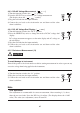
1) Turn the function switch to the “
• ” position.
Press the SELECT key to select Diode test.
(The display shows the symbol.)
2) Plug the test leads into the input terminals.
3)Connectthe test leadsto the diode andthenread thevalue when it
stabilizes.
Test leads
RedBlack
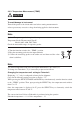
<Forward-bias Diode Test>
Connect the black test lead to the cathode and the red test lead to the anode.
Silicon diodes should give a reading of approximately 0.5V and light-emitting diodes a reading
between approximately 1.5V and 2.0V.
<Reverse-bias Diode Test>
Connect the black test lead to the anode and the red test lead to the cathode.
Normally, the display shows the “ OL ” symbol, indicating that the diode under test is normal.
The diode is defective if the display gives a certain voltage level.
Black test
lead
Red test
lead
Figure 1 Forward-bias
Diode Test
Red test
lead
Black test
lead
Figure 2 Reverse-bias
Diode Test