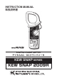
INSTRUCTION MANUAL 取扱説明書 DIGITAL CLAMP METER デジタルAC/DCクランプメータ KEW SNAP SERIES KEW SNAP 2009R
Contents 1.Safety Warnings ・・・・・・・・・・・・・・・・・・・・・・・・・・・・・・・・・・・・・・・・ 2.Features ・・・・・・・・・・・・・・・・・・・・・・・・・・・・・・・・・・・・・・・・・・・・・・・ 3.Specifications ・・・・・・・・・・・・・・・・・・・・・・・・・・・・・・・・・・・・・・・・・・ 4.Instrument Layout ・・・・・・・・・・・・・・・・・・・・・・・・・・・・・・・・・・・・・・・ 5.Preparation for Measurement ・・・・・・・・・・・・・・・・・・・・・・・・・・・・ 5−1 Checking Battery Voltage ・・・・・・・・・・・・・・・・・・・・・・・・・・ 5−2 Checking Switch Setting and Operation ・・・・・・・・・・・・・ 6.Measurement ・・・・・・・・・・・・・・・・・・・・・・・・・・・・・・・・・・・・・・・・・・・ 6−1 DC Current Measurement ・・・・・・・・・
1. Safety Warnings ○This instrument has been designed and tested according to IEC Publication 61010: Safety Requirements for Electronic Measuring Apparatus. This instruction manual contains warnings and safety rules which must be observed by the user to ensure safe operation of the instrument and retain it in safe condition. Therefore, read through these operating instructions before starting using the instrument.
Following symbols are used on the instrument and in the instruction manual. Attention should be paid to each symbol to ensure your safety. # Refer to the instructions in the manual. This symbol is marked where the user must refer to the instruction manual so as not to cause personal injury or instrument damage. Indicates an instrument with double or reinforced insulation.
WARNING ●Never attempt to make any measurement, if the instrument has any structural abnormality such as cracked case and exposed metal part. ●Do not turn the function selector switch with plugged in test leads connected to the circuit under test. ●Do not install substitute parts or make any modification to the instrument. Return the instrument to Kyoritsu or your distributor for repair or re-calibration. ●Do not try to replace the battery if the surface of the instrument is wet.
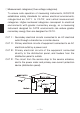
○Measurement categories (Over-voltage categories) To ensure safe operation of measuring instruments, IEC61010 establishes safety standards for various electrical environments, categorized as CATⅠ to CATⅣ, and called measurement categories. Higher-numbered categories correspond to electrical environments with greater momentary energy, so a measuring instrument designed for CATⅢ environments can endure greater momentary energy than one designed for CATⅡ.
2.Features ●Tear-drop-shaped jaws for ease of use in crowded cable areas and other tight places. ●Accurate true-RMS reading of AC current or voltage with distorted waveform. ●Average function for easy reading of input with large variation. ●Auto-null function for easy zero adjustment. ●Provides frequency reading in AC current or voltage measurement. ●Auto-ranging feature on current, voltage and resistance ranges. ●Wide measuring range from 0 up to 2000A.
*Effective Value (RMS) Most alternating currents and voltages are expressed in effective values, which are also referred to as RMS (Root-Mean-Square) values. The effective value is the square root of the average of square of alternating current or voltage values. Many clamp meters using a conventional rectifying circuit have "RMS" scales for AC measurement. The scales are, however, actually calibrated in terms of the effective value of a sine wave though the clamp meter is responding to the average value.
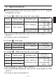
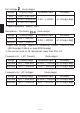
3.Specifications ●Measuring Ranges and Accuracy (at 23 ℃ ± 5 ℃ , relative humidity75% or less) AC Current (RMS value detection, Auto-range) Range Display range 400A 0.0∼420.0A 2000A 150∼2100A Accuracy※ (Frequency) ±1.3%rdg±3dgt (45∼66Hz) 0.0∼1700Arms ±2.0%rdg±5dgt (20Hz∼1kHz) 1700∼2000Arms ±2.3%rdg±3dgt (3000Apeak or less) (45∼66Hz) Allowable input ※For non-sinusoidal waveforms, add ±(1.5% of full scale), for Crest factor<3.
DC Voltage (Auto-range) Range Display range 40V 0.00∼±42.00V 400V ±15.0∼±420.0V 1000V ±150∼±1050V Allowable input Accuracy 0.00∼±1000V ±1.0%rdg±2dgt ※Input Impedance:approx. 2MΩ Resistance / Continuity Range Display range 400Ω 0.0 ∼ 420.0Ω 4000Ω 150 ∼ 4200Ω (Auto-range) Allowable input Accuracy 0.0Ω∼ 4000Ω ±1.5%rdg±2dgt ※Open-loop Voltage:approx.3V, Measuring Current : 0.6mA or less (400Ωrange) 0.06mA or less(4000Ωrange) ※The buzzer turns on for resistances lower than 20±1Ω.
Output Output voltage: 0.1mV / 1count Range DC400A Allowable input Output Voltage (mVDC) 0.0∼±400.0A 0∼±400mV DC2000A 0∼±2000A 0∼±200mV AC400A 0.0∼400.
●Operating System ●Display ●Overrange Indication ●Response Time ●Sample Rate ●Location for use ●Temperature and Humidity for Guranteed Accuracy ●Operating Temperature and Humidity ●Storage Temperature and Humidity ●Power Source ●Current Consumption ●Auto-power-off function ●Overload Protection ●Withstand Voltage ●Insulation Resistance ●Conductor Size ●Dimensions ●Weight ●Accessories ●Optional Accessories ΔΣ modulation Liquid crystal display with a maximum count of 4200 plus annunciators "OL" is shown on
4.Instrument Layout ① ⑮ ② ③ ④ ⑭ ⑦ ⑤ ⑥ ⑫ ⑨ ⑧ ⑩ ⑪ ⑬ ①Transformer Jaws Pick up current flowing through the conductor. ②Jaw Trigger Operates the transformer jaws. Press to open the Transformer Jaws. ③Function Selector Switch Selects function. Also used to power the instrument on. ④Data Hold Button Freezes the display reading. "H" is shown on the display when Data Hold is enabled. When the plug is inserted into the output terminal, Data Hold Switch operates as range selection switch.
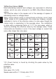
⑤Mode Selector Button Selects measuring mode. The instrument defaults to the normal mode (NOR). Then, press this switch to cycle through measuring modes. In any mode, pressing this switch for more than one second returns the instrument to the normal mode. A /V A /V ACA/ACV Display DCA/DCV Normal Normal Average Resistance Ω Average Peak Frequency Ω Resistance Display Continuity Display Continuity check Peak Hz ⑥Zero Adjust/Reset Button Used for zero adjustment on DCA and resistance ranges.
⑧Terminal Cover Slides over V/Ω and COM Terminals to prevent access to them when OUTPUT terminal is in use. ⑨OUTPUT Terminal(For AC or DC current range only) Provides DC voltage output in proportion to the AC or DC current reading. The output is connected to a recording device such as a chart recorder for long hour monitoring. No output is available on voltage and resistance ranges. ⑩COM Terminal Accepts the black test lead for voltage or resistance measurement.
5.Preparation for Measurement 5-1 Checking Battery Voltage ①Set the function selector switch to any position other than "OFF". ②When the display is clear without "BATT" showing, proceed to measurement. ③When the display blanks or "BATT" is indicated, replace the battery according to section 8. Battery Replacement. NOTE ● The Auto-power-off feature automatically turns the instrument off in about 10 minutes after the last switch or button operation.
6.Measurement 6-1 DC Current Measurement DANGER ●Do not make measurement on a circuit above 1000VDC. This may cause shock hazard or damage to the instrument or equipment under test. ●Do not make measurement with the battery compartment cover removed from the instrument. ●Do not make current measurement with the test leads connected to the V/Ω and COM terminals. ●Keep your fingers and hands behind the barrier during measurement. Correct Wrong ①Set the function selector switch to the " A" position.
NOTE ● During current measurement, keep the transformer jaws fully closed. Otherwise, accurate measurement cannot be made. The maximum measurable conductor size is approx. 55mm in diameter. ● When the current flows from the upside (the display side) to the underside of the instrument, the reading is indicated positive. ● The Zero Adjust/Reset button may not completely zero adjust the output voltage from the OUTPUT terminal. In this case, make zero adjustment on the recording device.
①Set the function selector switch to the " ∼ A" position.“AC" should be shown on the upper left corner of the display. ②Press the trigger to open the transformer jaws and clamp them onto a single conductor and take the reading on the display. The most accurate reading will be obtained by keeping the conductor at the center of the transformer jaws. NOTE ● During current measurement, keep the transformer jaws fully closed. Otherwise, accurate measurements cannot be taken.
①Set the function selector switch to the "V" position.“DC" should be shown on the upper left corner of the display. ②Slide the terminal cover to the left to disclose the V/Ω and COM terminals. Plug the red test lead into the V/Ω terminal and the black test lead into COM terminal. ③Connect the tip of the red and black test leads to the positive (+) and negative (-) sides of the circuit under test respectively. Take the reading on the display.
③Connect the tip of the red and black test leads to the circuit under test and take the reading on the display. NOTE ● When the voltage under test measures 3% of the range or less, or the frequency of the voltage is low, "LoHz" is indicated on the display. 6-5 Resistance Measurement DANGER ●Never use the instrument on an energized circuit. ●Do not make measurement with the battery compartment cover removed. ●Keep your fingers and hands behind the barrier during measurement. Ω" position.
6-6 Continuity Check (400Ω range fixed) ※The continuity check mode is enabled by pressing the mode " is indicated on the selector switch on resistance range. " display to show the instrument in the continuity check mode. The buzzer beeps, if the resistance under test is 20.0Ω or less. DANGER ●Never use the instrument on an energized circuit. ●Do not make measurement with the battery compartment cover removed. ●Keep your fingers and hands behind the barrier during measurement.
DANGER ●Never use the instrument on a high voltage circuit above 750VAC. This may cause electrical shock hazard and damage to the instrument or the circuit under test. ●Do not make measurement with the battery compartment cover removed. ●Do not make current measurement with the test leads plugged into the instrument. ●Keep your fingers and hands behind the barrier during measurement. ①Set the function selector switch to the " ∼ A" or " ∼ V" position.
DANGER ●Never use the instrument on a circuit above 750VAC/1000VDC. This may cause electrical shock hazard and damage to the instrument or the circuit under test. ●Do not make measurement with the battery compartment cover removed. ●Do not make measurement with the test leads plugged into the instrument. ●Keep your fingers and hands behind the barrier during measurement. ①The PEAK mode is available on DCA, ACA, DCV and ACV ranges. Set the function selector switch to the desired position.
NOTE ● In the PEAK mode, the auto-ranging feature is disabled and measuring ranges are fixed as follows. DC/ACA: 0-400.0A DC/ACV: 0-400.0A ● When a measured value is 9 counts or less, it is corrected to 0 ● The Auto-power-off function is disabled in the PEAK mode as well. 6-9 Average Measurement ●In the Average mode, "AVG" is indicated on the display. ●The display reads a running average of six readings over an interval of about 2 seconds. ●This mode is available on ACV, DCV, ACA and DCA ranges.
7.Other Functions 7-1 Auto-power-off Function CAUTION ●The instrument consumes small amount of battery power in the Auto-power-off mode. Make sure to set the function selector switch to the OFF position after use. This is a function to prevent the instrument from being left powered on in order to conserve battery life. This function causes the instrument to enter the Auto-power-off mode about 10 minutes after the last switch or button operation.
NOTE ● If the instrument in the Data Hold mode goes into "Auto-poweroff," it will return to the normal mode. 7-3 LoHz Function In ACV or ACA range, if frequency of the voltage or current under test is 40Hz or lower, the display indicates "LoHz". "LoHz" is also indicated where input is 3% of range or less. 7-4 OUTPUT Terminal (For current ranges only) DANGER ●Never use the instrument on a circuit above 750VAC/1000VDC.
②Slide the terminal cover to the right to disclose the OUTPUT terminal and insert the output plug into the terminal. Make connection to the recording device. ③When the plug is inserted into the output terminal, auto-range function is cleared. Set the range depending on the state of Data Hold Switch. Data Hold Switch OFF 400A range Data Hold Switch ON 2000A range Note:After measurement, be sure to return Data Hold Switch to OFF position.
● Consult the output voltage specifications shown in section 3 and adjust the sensitivity of the recording device. ● For long hours of use of the OUTPUT terminal, use an Alkaline battery, which will extend continuous recording time up to about 35 hours.
8.Battery Replacement WARNING ●To avoid electric shock hazard, make sure to set the function selector switch to "OFF" and remove the test leads from the instrument before trying to replace battery. CAUTION ●Do not mix new and old battery. ●Make sure to install battery in correct polarity as indicated in the battery compartment. If the battery voltage becomes too low for the instrument to operate normally, " " is shown on the display. Then, replace the battery.
9.Optional Accessories ● MODEL 8008 (For AC current measurement only) Multi-Tran Model 8008 is designed to increase the measuring capability of a clamp meter. With the use of the Multi-tran, you can not only extend current range over 3000A, but also clamp on a large bus-bar or conductor. ①Set the function selector switch to the " ∼ A" position . ②As shown in the figure below, clamp KEW SNAP 2009R onto the pickup coil of MODEL 8008. ③Clamp MODEL 8008 onto the bus-bar or conductor under test.
Memo ̶ 30 ̶
DISTRIBUTOR Kyoritsu reserves the rights to change specifications or designs described in this manual without notice and without obligations.