
User guide

̶
20
̶
6-6 Continuity Check (400Ω range fixed)
※ The continuity check mode is enabled by pressing the mode
selector switch on resistance range. "
" is indicated on the
display to show the instrument in the continuity check mode. The
buzzer beeps, if the resistance under test is 20.0Ω or less.
DANGER
●Never use the instrument on an energized circuit.
● Do not make measurement with the battery compartment cover
removed.
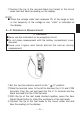
● Keep your fingers and hands behind the barrier during
measurement.
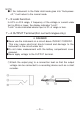
①Set the function selector switch to the " Ω" position.
② Slide the terminal cover to the left to disclose the V/Ω and COM
terminals. Plug the red test lead into the V/Ω terminal and the
black test lead into the COM terminal.
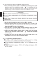
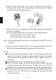
③ With the tip of the test leads shorted together, press the Zero
Adjust/Reset button to offset the resistance of the test leads.
④ Press the mode selector button once to enter from the normal
mode to the continuity check mode. " " should be indicated
on the display.
⑤ Connect the tip of the test leads to the circuit under test. If the
resistance is 20.0Ω or less, the buzzer beeps.
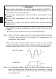
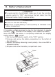
6-7 Frequency Measurement
● On ACA or ACV range, the frequency of the current or voltage
under test can be counted and shown on the display.
● In the frequency measurement mode, "Hz" is indicated on the
display.
● Trigger threshold is approx. 10
V for AC voltage and approx. 40A
for AC current.