INSTRUCTION MANUAL DIGITAL CLAMP METER KEW SNAP Series KEW SNAP 2413R KYORITSU ELECTRICAL INSTRUMENTS WORKS,LTD.
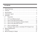
Contents 1.Safety Warnings ………………………………………………………1 2.Features ………………………………………………………………4 3.Specifications …………………………………………………………5 4.Instrument Layout ……………………………………………………9 5.Operation 5-1 Preparation ………………………………………………………11 5-2 AC Current Measurement………………………………………11 5-3 How to Use Peak Hold Function ………………………………14 5-4 How to Use The Frequency Selector Switch …………………16 5-5 How to Use Data Hold Function ………………………………17 5-6 How to use Back Light …………………………………………17 5-7 Analogue Output How to Use Model 7073 Output
1.Safety Warnings Make sure to read through this instruction manual before using this instrument. ●The instrument has been designed, manufactured, and tested according to: IEC 61010, pollution degree 2, CAT.Ⅲ, 300V IEC 61010, pollution degree 2, CAT.Ⅱ, 600V This instruction manual contains warnings and safety rules which must be observed by the use to ensure safe operation of the instrument and to retain it in safe condition.
Following symbols are used on the instrument and in the instruction manual. Attention should be paid to each symbol to ensure your safety. Refer to the instructions in the manual. This symbol is marked where the user must refer to the instruction manual so as not to cause personal injury or instrument damage. Indicates an instrument with double or reinforced insulation.
CAUTION ●Make sure that the function selector switch is set to an appropriate position before making measurement. ●Be sure to set the function selector switch to the “OFF” position after use. When the instrument will not be use for a long period of time, place it in storage after removing the battery. This is to avoid damage to the instrument by possible leakage from the battery. ●Do not expose the instrument to the direct sun, extreme temperatures or dew fall.
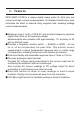
2.Features KEW SNAP 2413R is a unique digital clamp meter for both very low current and high current measurements. Its shielded transformers jaws minimizes the effect of external stray magnetic field, enabling leakage current measurements. ●Measures from 0.1mA to 1000A AC and provides frequency response higher than 1kHz on all measuring ranges. Measurements also possible with approximately -7% accuracy at 20 kHz on 200mA range.
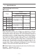
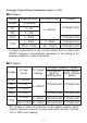
3.Specifications Measuring Ranges and Accuracy ●AC Current Accuracy Ranges Frequency Range Response WIDE * Add 2% at CF≧2 0∼199.9mA CF≦3.0 0∼1.999A 2A CF≦3.0 0∼19.99A 20A CF≦3.0 0∼199.9A 200A CF≦3.0 0∼500A CF≦3.0 1000A 501∼1000A CF≦3.0 50/60Hz * only sine wave Time Limit for Measurements 200mA ±1.8%rdg±5dgt (50/60Hz) ±2.5%rdg±5dgt ±3.0%rdg±5dgt (40∼1kHz) Continuous ±2.0%rdg±5dgt (50/60Hz) ±3.0%rdg±5dgt ±3.5%rdg±5dgt (40∼1kHz) ±5.0%rdg (50/60Hz) ±5.5%rdg 10min.
―6―
Analogue Output (Output impedance: Approx. 1kΩ) ●AC Output Range Measuring Range 200mA 0∼200mA 2A 0∼2A 20A 0∼20A 200A 0∼200A 1000A AC Output Voltage 0∼200mV Accuracy ±2.0%rdg±0.5mV ±2.5%rdg±0.5mV 0∼500A 0∼50mV ±3.0%rdg±0.5mV 501A∼1000A 50∼100mV ±5.0%rdg±0.5mV *Voltage proportional to the current under test is output with “WIDE”frequency characteristics regardless of the setting of the frequency Selector or peak hold switch.
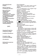
Operating System Display Range selection Overrange Indication Response Time Sample Rate Data Hold Location for use Temperature & Humidity for Specified Accuracy Storage Temperature & Humidity Operating Temperature & Humidity Power Source Low Battery Warning Current Consumption Standard(Safety) (EMC) Overload Protection Withstand Voltage Insulation Resistance Conductor Size Dimensions/Weight Accessories Optional Accessories Peak Hold :Dual Integration :Field effect 3・1/2 digit liquid crystal display with m
4.Instrument Layout ⑦ ⑩ ① ② ⑥ ⑪ ⑤ LCD ⑧ ⑨ ④ over range indication ③ Fig.2 ① LCD Field effect liquid crystal display with maximum indication of 1999. Function symbol(mA, A) and decimal point automatically appear as the function / range switch is turned.
“ ”is displayed on the lower right side for low battery warning and “1”is displayed only at the highest digit for overrange indication. ② Data Hold Button Allows for easy reading in dimly lit or hard-to-reach-locations. The display can be observed away from the conductor after pushing in the button. Data hold can be released by pushing the button again after the reading is taken. Symbol“ ”is displayed on the LCD.
5.Operation 5-1 Preparation (1) To Check battery set the function/range switch ⑤ To the desired position. If the display is clear without symbol “ ”showing, battery voltage is sufficient. If the display blanks or“ ”is indicated, replace the battery in accordance with the battery replacement procedures as described in section 6. Note:“ ”also appears on the display when the battery becomes exhausted during use. Replace with a new battery.
CAUTION ●Transformers jaws , especially their tips, have been precisely adjusted to obtain maximum accuracy. Take sufficient care to avoid shock, vibration or excessive force when handing the instrument. ●When a foreign substance is stick in the jaw tips or they cannot properly engage, the transformer jaws do not fully close. In such a case, do not release the jaw trigger suddenly or attempt to close the transformer jaws by applying external force.
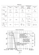
Fig.3 Normal AC Current Measurements Fig.4 Earth Leakage Current Measurements Single-Phase 2-wire system (in 3-wire system with neutral clamp onto all 3 wire) 3-phase 3-wire system. (in 4-wire system with neutral clamp onto all 4 wire) Fig.5 Measurements out of balance Leakage Note:When measuring large current, observe the time limit specified in section 3, Specifications. Otherwise, the transformers jaws may overheat, resulting in damage to the instrument.
5-3 How to Use Peak Hold Function 10ms or 100ms response time can be selected for peak hold measurement. Make selection according to your application needs. (1) With the transformer jaws clamped onto the conductor under test, slide the peak hold switch from the OFF position to the desired peak response time position. Symbol “ ” is displayed on the LCD. (2) The peak hold display reads 1/√2 of the peak current value.
Note 2:If it is necessary to read the display away from the conductor in a peak hold measurement, press the data hold switch ② first and then remove the instrument from the conductor. Otherwise, the peak hold reading may be higher than the actual value due to the electrical noise caused by the opening and closing of the transformer jaws. Press the data hold switch again for a reset.
Note 3:The peak hold circuit of this instrument may not capture some signals depending on phases because a half-wave rectifier circuit is used. Response characteristics are 10ms/ 100ms. Noises on higher frequencies caused by inverters may not be captured. Readings with Peak Hold off might become smaller or zero when activating the Peak hold function, but this is not a malfunction.
Note:Selection with the frequency selector switch dose not apply to AC output of the two-way analogue output. DC output of the twoway analogue output reflects the frequency selector switch setting. Refer to Figure. 1 for frequency characteristics. 5-5 How to Use Data Hold Function Push in the Data Hold button to freeze the reading. This is especially useful for taking a reading in a dimly lit or hard-to-reach locations. The display can be observed away from the conductor.
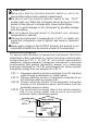
5-7 Analogue Output: How to Use Model 7073 Output Cord AC and DC output can be obtained by inserting optional Model 7073 output cord into the two-way analogue output terminal ③. AC Output: Can be monitored by connecting a digital multimeter to analogue output terminal or observed as a waveform by connecting an oscilloscope. DC Output: Can be monitored by connecting a digital multimeter, or a recorder, which enables many hours of monitoring. See Figure 8.
6.Battery Replacement Replace the battery when“ ”symbol appears on the LCD. (1) Set the function/range switch to the OFF position. (2) Unscrew and remove the battery compartment cover from the rear of the case. (3) Install a new 9V battery of type 6F22 or equivalent observing correct polarity. (4) Screw the battery compartment cover. WARNING Never replace the battery during measurement.
7.Cleaning Use a damp cloth detergent for cleaning the body of the instrument. To avoid possible deforming or discoloring, do not use solutions containing solvent. CAUTION ●Never use paint thinner, benzene or other solutions containing solvent for cleaning the instrument. Otherwise, deforming or discoloring of the instrument body may result. ●Handle the instrument with care and follow the instructions in order to maintain it in good condition for a long period of time.
8.Before Sending for Repair Use the following troubleshooting guide for hints on problems with instrument operation. Condition Possible Cause Display blanks after power- Battery on. is Remedy improperly Install the battery correctly. installed. Replace the battery. Battery is exhausted. Display reading remains Data hold button is pressed Release data hold button. frozen. in. Set peak hold switch to Peak hold switch is at ON OFF position. position.
DISTRIBUTOR Kyoritsu reserves the rights to change specifications or designs described in this manual without notice and without obligations.