INSTRUCTION MANUAL ALL WEATHER DIGITAL AC LEAKAGE CURRENT TESTER KEW SNAP Series MODEL 2417
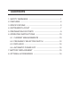
CONTENTS 1. SAFETY WARNINGS ・・・・・・・・・・・・・・・・・・・・・・・・・・・・・・・・・・・・1 2. FEATURES ・・・・・・・・・・・・・・・・・・・・・・・・・・・・・・・・・・・・・・・・・・・・・4 3. SPECIFICATIONS ・・・・・・・・・・・・・・・・・・・・・・・・・・・・・・・・・・・・・・5 4. INSTRUMENT LAYOUT ・・・・・・・・・・・・・・・・・・・・・・・・・・・・・・・・・7 5. PREPARATION FOR TESTS ・・・・・・・・・・・・・・・・・・・・・・・・・・・・・9 6.
1. SAFETY WARNINGS Make sure to read through this instruction manual before using this instrument. This instruction manual contains warnings and safety rules which must be observed by the use to ensure safe operation of the instrument and to retain it in safe condition. ●The symbol indicated on the instrument means that the user must refer to related parts in the manual for safe operation of the instrument. Be sure to carefully read the instruction following each symbol in this manual.
Following symbols are used on the instrument and in the instruction manual. Attention should be paid to each symbol to ensure your safety. Refer to the instructions in the manual. This symbol is marked where the user must refer to the instruction manual so as not to cause personal injury or instrument damage. Indicates an instrument with double or reinforced insulation. DANGER ●Never make measurement on a circuit above 600V AC.
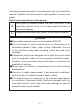
WARNING ●Never attempt to make any measurement if any abnormal conditions are noted, such as broken case, cracked test leads and exposed metal parts. ●Do not install substitute parts or make any modification to the instrument. Return the instrument to Kyoritsu or your distributor for repair or re-calibration. ●Do not try to replace the battery if the surface of the instrument is wet. CAUTION ●Make sure that the function selector switch is set to an appropriate position before making measurement.
2. FEATURES ○ Model 2417 offers True RMS measurement capability. ○ Designed for measurements of AC Leakage and AC current with five ranges from 200 mA to 500 A. AC 200 mA range provides a high resolution of 0.1 mA. ○ Least affected by external magnetic field. ○ Provides dual frequency responses of fundamental 50/60Hz only or up to 1kHz. The frequency response of up to 1kHz permits measurements of current with harmonics superimposed on the fundamental frequency.
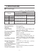
3. SPECIFICATIONS ●AC current ranges at 23±10℃ , 85% relative humidity Ranges 200mA 2000mA 20A 200A 0-199.9mA 0-1999mA 0-19.99A 0-199.9A 500A 0-500A Accuracy Frequency Selector Switch WIDE (40Hz-1kHz) position 50/60 Hz position ±1.0% rdg±4 dgt (50/60 Hz) ±1 .5% rdg±6 dgt ±3.0% rdg±4 dgt (40Hz-1kHz) ±1.5% rdg±4 dgt (50/60 Hz) ±2.0% rdg±6 dgt ±3.5% rdg±4 dgt (40 Hz-1kHz) ±2.0% rdg±4 dgt (50/60 Hz) ±2.5% rdg±6 dgt ±4.
Auto Power Off: Insulation Resistance: Withstand Voltage: Conductor Size: Dimensions: Weight: Accessories: Optional Accessories: Automatically turns power off in approx. 30 minutes after the instrument is powered 10MΩ min. at 1000 V between electrical circuit and housing case, and electrical circuit and transformer jaws 3700 V AC for 1 minute between electrical circuit and housing case as well as electrical circuit and transformer jaws Approx. 40 mm diameter max.
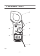
4. INSTRUMENT LAYOUT Fig.
① Transformer Jaws Pick up current flowing through the conductor. ② Jaw Trigger Operates the transformer jaws. Press to open them. ③ Power/Range Switch Selects ranges. Also, turns power on. Always turn the switch to off after use. ④ Data Hold Push Button Push to freeze a reading and push again to release it. In Data Hold mode, "H" is displayed on the digital display. ⑤ Frequency Selector Switch Selects frequency response of 50/60 Hz or up to 1 kHz WIDE.
5. PREPARATIONS FOR TESTS WARNING Always inspect your instrument and accessories for any sign of damage or abnormality before every use. If any abnormal conditions exist (eg. cracked cases, display not reading, etc.), do not attempt to conduct any tests. 5-1 Battery Check To check the battery voltage set the Power/Range Selector Switch to OFF position. If the display is clear without symbol "B" showing, battery voltage is OK.
6. OPERATING INSTRUCTIONS 6-1 Current Measurements WARNING ● Do not make measurements where the potential is greater than 600 V AC. This may cause shock hazard and damage to the instrument or equipment under test. ● The Transformer Jaws are made of metal and their tips are not insulated. Be especially careful about the hazard of possible shorting where the equipment under test has exposed metal parts. ● Do not open the battery compartment cover when making measurements.
NOTE ● When making current measurements, keep the Transformer Jaws fully closed. Otherwise, accurate measurements cannot be taken. Maximum conductor size is 40 mm in diameter. ● When measuring larger current, the Transformer Jaws may buzz. This is not a fault and does not affect the accuracy either. (1) Set the Range Switch to the desired "A" or " mA" position. (2) Select the desired frequency response. WIDE or 50/60 Hz, with the Frequency Selector Switch.
NOTE ● For more accurate measurements, place the conductor at the center of the closed jaws. ● When measuring current on a line or a grounded wire, clamp onto one conductor only. (4) When measuring out of balance leakage current, clamp onto all conductors except a grounded wire as shown in Fig. 4. Fig. 4 6-2.
Frequency response of 40 Hz to 1 kHz permits measurements of current with harmonics superimposed on the fundamental frequency. High frequency current from appliances such as inverters, switching regulators etc. can therefore be measured. NOTE ● Model 2417 hasa very good frequency response due to the electrical property of the transformer jaws used for the instruments.
6-3 Date Hold Push the Data Hold Switch Button to freeze the reading. "H" symbol is displayed on the digital display to indicate that the instrument is in Data Hold mode. Push the button again to exit from Data Hold mode. 6-4 Automatic Power Off Model 2417 automatically turns power off In approx. 30 minutes after it is turned on. To operate the instrument, set the Frequency Selector Switch back to OFF position and then ON position.
7. BATTERY REPLACEMENT 7-1 When to replace the battery (1) When "B" symbol is displayed on the digital display. (2) When the digital display does not read with the Power/Range Selector Switch set to ON position. 7-2 Battery replacement (1) Set the Power/Range Selector Switch to OFF position. (2) Unscrew and remove the battery compartment cover as shown in Fig. 5. (3) Replace the battery with a new 9 V battery type 6F22 or equivalent, observing correct polarity. (4) Screw the battery compartment cover. Fig.
8. OPTIONAL ACCESSORIES 8-1 Model 8004 and 8008 (Multi-Tran) Model 8008 is a clamp-on current transformer designed to measure A C c u r r e n t u p t o 3000 A i n conjunction with a clamp meter. It clamps on large bus-bars (up to 150 X 100 mm) and conductors ( u p t o 100 m m d i a m e t e r ) . Model 8004 is also available for AC current measurements up to1000A on a conductor of max. 60 m m d i a m e t e r.
MEMO ̶ 17 ̶
DISTRIBUTOR 07-02 92-1313A