INSTRUCTION MANUAL KEW3121A, 3122A KEW3123A HIGH VOLTAGE INSULATION TESTER KEW 3121A, 3122A, 3123A
CONTENTS Page 1.Features …………………………………………………………1 2.Specifications ……………………………………………2 ∼ 3 3.Instrument Layout ………………………………………………4 4.Operating Instructions …………………………………………5 4-1.Mechanical Zero Adjustment ……………………………5 4-2.Battery Check ……………………………………………5 4-3.Insulation Resistance Measurement 4-4.Continuous Measurement 4-5.Use of Guard Terminal ……………………6 ………………………………6 …………………………………7 5.Battery Replacement ………………………………………8 6.Accessories and options ………………………………………8 6-1.
1. Features ● ● ● ● ● ● ● Battery powered, the instruments test insulation up to 100000MΩ at 2500V for KEW 3121A, 200000MΩ at 5000V for KEW 3122A and 200GΩ at 5000V and 400GΩ at 10000V for KEW 3123A. Suited for heavy duty electrical maintenance and servicing of industrial installations, cables, transformers, generators and switchgear where high voltage insulation tests are required. Dual scales for low an d high ranges which change automatically.
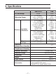
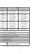
2. Specifications DC Test Voltage Measuring Ranges Accuracy Insulation Resistance Output Voltage Operating Temperature & Humidity Storage Temperature & Humidity Insulation Resistance Withstand Voltage KEW 3121A KEW 31 2500V 5000 V 0∼2000MΩ/ 1000∼100000MΩ (automatic change) 0∼5000 M 2000∼ 20 (automatic ch ±5% of reading (100∼50000MΩ) ±10% of reading or 0.5% of scale length ( ranges other than listed above) at 23℃ ±5℃ ±10% of reading (100∼50000MΩ) ±20% of reading or 1.
W 3122A 0 V KEW 3123A 5000V 10000V 00 MΩ/ ∼ 200000MΩ tic change) 0∼5GΩ/2∼200GΩ (automatic change) 0∼10GΩ/4∼400GΩ (automatic change) of ∼ of of es ed ℃ of ∼ of of es ed ℃ V ∼ ±5% of reading (0.2∼100GΩ) ±10% of reading or 0.5% of scale length ( ranges other than listed above) at 23℃ ±5℃ ±10% of reading (0.2∼100GΩ) ±20% of reading or 1.0% of scale length ( ranges other than listed above) at −10℃∼+40℃ 5000V ±5% (0.2~100GΩ) ±5% of reading (0.4∼200GΩ) ±10% of reading or 0.
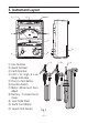
3. Instrument Layout ③ ② ① ④ ④ ⑦ ⑧ ⑥ ⑤ ① Line Terminal ② Guard Terminal ③ Earth Terminal ④ LED's for High & Low Range Indication ⑤ Press to Test Button ⑥ Function Switch ⑦ Meter Movement Zero Adjust ⑧ Battery Compartment Cover ⑨ Line Probe (Red) ⑩ Earth Cord (Black) ⑪ Guard Cord (Green) ⑪ Fig.
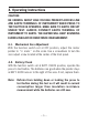
4. Operating Instructions CAUTION: BE CAREFUL ABOUT HIGH VOLTAGE PRESENT ACROSS LINE AND EARTH TERMINALS OF INSTRUMENT WHEN PRESS TO TEST BUTTON IS OPERATED. MAKE SURE TO EARTH CIRCUIT UNDER TEST. ALWAYS CONNECT EARTH TERMINAL OF INSTRUMENT TO EARTH. THE BUZZER WILL KEEP SOUNDING DURING INSULATION RESISTANCE MEASUREMENT. 4-1. Mechanical Zero Adjustment With the function switch set at OFF position, adjust the meter pointer to“∞ mark ”on the scale.
4-3. Insulation Resistance Measurement With the function switch set at OFF position, always connect the circuit under test to earth. Attach the test lead to the earth terminal of the instrument and connect to the earthed side of the circuit under test. With the function switch set at 2500V and 5000V for KEW 3121A and 3122A or 5000V or 10000V for KEW 3123A, place the line probe in contact with the circuit under test and operate the press to test button.
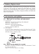
4-5. Use of Guard Terminal When measuring the insulation resistance of a cable, Ieakage current flowing on the surface of cable jacket and the current flowing inside the insulator are mixed and may cause error in insulation resistance value. In order to prevent such error, wind a conductive wire around the point where leakage current flows. Then connect it to the Guard terminal as shown in below Fig.2.
5. Batttery Replacement Remove the battery compartment cover by loosening the screw located on the back of the housing case. Replace the whole battery pack. Alkaline batteries are recommended where the instrument is used at a temperature below the freezing point. The ordinary manganese batteries will deteriorate below the freezing point. 6. Accessories and options 6-1.
To recorder To shield or Earth Fig.3 7. Cleaning Meter Cover This earth tester is managed by our company's quality standard and is delivered in the best condition after passed the inspection. But in the dry time of winter static electricity sometimes builds up on the meter cover due to the characteristic of plastic. When the pointer deflects by touching the surface of this tester or zero adjustment can not be made, do not try to make measurement.
DISTRIBUTOR Kyoritsu reserves the rights to change specifications or designs described in this manual without notice and without obligations.