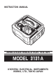
INSTRUCTION MANUAL ANALOGUE INSULATION TESTER MODEL 3131A KYORITSU ELECTRICAL INSTRUMENTS WORKS,LTD.
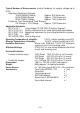
Contents 1. Safety Precautions ................................................................................ 1 2. Features ............................................................................................... 3 3. Specifications ...................................................................................... 4 4. Instrument Layout ................................................................................. 6 5. Preparation for Testing ...............................................
1. Safety Precautions ○ The instrument is designed and tested in accordance with the following standards and supplied in the best condition. ・IEC 61010-1 ・IEC 61010-2-31 ・IEC 61557-1/2/4 ・IEC 60529(IP54) ・IEC 61326 Overvoltage CAT.
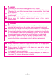
DANGER ● Do not use this instrument on energized (LIVE) circuits. ● Do not make measurement in the presence of flammable gasses. Otherwise, the use of the instrument may cause sparkling, which leads to an explosion. ● Always keep your fingers behind the barrier on test probe during measurement. ● Never use the instrument if its surface or your hand is wet. ● Never open the battery compartment cover while making measurement.
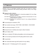
2. Features MODEL-3131A is an analogue insulation tester with five ranges for insulation resistance measurement and continuity testing (resistance tests) of low voltage installations.
3. Specifications ● Measuring Range and Accuracy (at 23±5° C, relative humidity 45-75%) Insulation Resistance Ranges:(IEC 61557-2) Nominal Output Voltage Measuring Ranges Open-Circuit Voltage Short-Circuit Current Nominal Current Accuracy 250V 0 - 100MΩ 500V 0 - 200MΩ 1000V 0 - 400MΩ 250V DC +20% max. 500V DC +20% max. 1000V DC + 20% max. 1.3mA approx 1mA DC min. 1mA DC min. 1mA DC min. at 0.5MΩ at 1MΩ at 0.25MΩ ±5% of indicated value ±5% of indicated value ±5% of indicated value at 0.1MΩ- 10MΩ at 0.
Typical Number of Measurements (central tendency for supply voltage up to 6.5V) Insulation Resistance Ranges: 1000V/400MΩ Range Approx. 500 times min. 500V/200MΩRange Approx. 1300 times min. 250V/100MΩ Range Approx. 1800 times min. Continuity Test (Resistance Test) Ranges: xΩ Range/ x 10Ω Range Approx. 1000 times min. Applicable Standards IEC 61010-1 Overvoltage CAT.
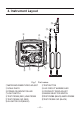
4. Instrument Layout ⑬ ⑪ ③ ④ ⑨ ⑫ ⑩ ⑤ ⑥ ② ① ⑦ ⑧ Fig.
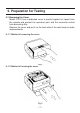
5. Preparation for Testing 5-1 Removing the Cover Model 3131A has a dedicated cover to protect against an impact from the outside and prevent the operation part, and the connector socket from becoming dirty. Remove the cover and put it on the back side of the main body to make measurements. 5-1-1 Method of removing the cover Fig.2 5-1-2 Method of housing the cover Fig.
5-2 Mechanical Zero Adjustment Check that the pointer lines up with the middle of the mark on the scale correctly. If not, adjust it by rotating the meter movement zero adjust with a screwdriver, etc. 5-3 Battery Voltage Check ① Set the range selector switch to BATT. CHECK position. ② Press the test button. ③ Then the pointer deflects. Judge the battery status with BATT.GOOD mark on the scale plate. If the pointer does not move to BATT.GOOD mark, the batteries are exhausted.
6. Operation 6-1 Disconnection and check of power source of circuit under test DANGER ● To avoid possible electrical shock, do not perform measurements on energized (LIVE) circuits. ● Never make measurements with the battery compartment cover removed. CAUTION ● Never press the test button if the live circuit warning LED is lit or the warning buzzer sounds. This may damage the circuit. Voltage check can be made with the range selector switch at any position.
6-2 Insulation Resistance Measurement DANGER ● Always test the circuit or equipment to ensure it is surely de-energized before measurement according to the instruction of 6-1. ● To avoid electrical shock, measurements must be performed on deenergized circuits only. ● When the test button is pressed with the range selector switch in the insulation position, take care not to touch the tip of the test probe and the circuit under test where a high voltage is present in order to avoid possible shock hazard.
DANGER Do not touch the circuit under test immediately after testing. Capacitance stored in the circuit may cause electric shock. Leave the test probe connected to the circuit and never touch the circuit until the discharge is completed. Principle of Insulation Resistance Measurement Resistance value can be obtained by applying a certain high voltage to the resistance (insulation resistance) and measuring the flowing current.
① Set the range selector switch to the desired position xΩor x 10Ω. ② Short the line probe (red) and the earth clip of the test probe (black) and press the test button. Adjust the ohm zero adjust to zero the pointer on the scale. ③ Connect the test probes to the circuit under test and press the test button. ④ Read the scale directly for xΩrange, multiply by 10 for x 10Ωrange. continuity Fig.
7. Back Light Function To facilitate working at night or dimly lit situations, a back light function is provided which illuminates the display. To operate this function, the back light button must be pressed and released while pressing the test button. The back light continues illuminating for approx. 40 seconds and then turn off automatically. When the test button is released, the back light will turn off even within the lighting time. Fig.
8. Battery & Fuse Replacement DANGER ● Never open the battery compartment cover while making measurement. To avoid possible electrical shock, disconnect the test probe before opening the cover for battery and fuse replacement. ● Replacement fuse must have the following rating. Fast acting type, F500mA/600V, φ6.35×32mm 8-1 Battery Replacement ① Disconnect the test probe from the instrument. ② Open the battery compartment cover by unscrewing the metal captive screw to reveal battery compartment.
9. Notes on Accessories 9-1 How to Fit Strap Belt and Test Probe Pouch By hanging the instrument around the neck, both hands can be used freely for easy and safety working. ① How to fit the strap belt Fig.9 How to fit the strap belt ② Whole diagram when the test probe pouch is attached Fig.
10. Cleaning of the Instrument ◎ Cleaning the meter cover This instrument is managed by our company's quality standard and is delivered in the best condition after passed the inspection. But in the dry time of winter static electricity sometimes builds up on the meter cover due to the characteristic of plastic. When the pointer deflects by touching the surface of this instrument or zero adjustment can not be made, do not try to make measurement.
MEMO ― 17 ―
DISTRIBUTOR 92-1487A 01-12 Kyoritsu reserves the rights to change specifications or designs Described in this manual without notice and without obligations. R KYORITSU ELECTRICAL INSTRUMENTS WORKS, LTD. No.5-20, Nakane 2― chome, Meguro-ku, Tokyo, 152-0031 Japan Phone: (03) 3723― 0131 Fax: (03) 3723― 0152 URL:http://www.kew-ltd.co.jp E-mail:info@kew-ltd.co.