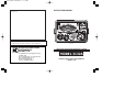
3132A-E/03-08 03.8.6 10:33 AM ページ 表4 INSTRUCTION MANUAL DISTRIBUTOR Kyoritsu reserves the rights to change specifications or designs described in this manual without notice and without obligations. KYORITSU ELECTRICAL INSTRUMENTS WORKS, LTD. ANALOGUE INSULATION-CONTINUITY TESTER MODEL 3132A No.5-20,Nakane 2-chome, Meguro-ku, Tokyo 152-0031 Japan Phone :(03) 3723-0131 Fax : (03) 3723-0152 URL : http://www.kew-ltd.co.jp E-mail : info@kew-ltd.co.
3132A-E/03-08 03.8.6 10:33 AM ページ 目1 CONTENTS 1.Safety Precautions …………………………………………………………… 1 2.Features ……………………………………………………………………… 4 3.Specifications ………………………………………………………………… 5 4.Instrument Layout …………………………………………………………… 8 5.Preparation for Testing ……………………………………………………… 9 5-1 Mechanical Zero Adjustment …………………………………………… 9 5-2 Battery Voltage Check ………………………………………………… 9 5-3 Test Probe Connection ………………………………………………… 9 5-4Test Probe check ………………………………………………………… 9 6.
132A-E/03-08 03.8.6 10:33 AM ページ 目1 CONTENTS 1.Safety Precautions …………………………………………………………… 1 2.Features ……………………………………………………………………… 4 3.Specifications ………………………………………………………………… 5 4.Instrument Layout …………………………………………………………… 8 5.Preparation for Testing ……………………………………………………… 9 5-1 Mechanical Zero Adjustment …………………………………………… 9 5-2 Battery Voltage Check ………………………………………………… 9 5-3 Test Probe Connection ………………………………………………… 9 5-4Test Probe check ………………………………………………………… 9 6.
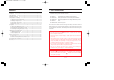
3132A-E/03-08 03.8.6 10:33 AM ページ 2 DANGER is reserved for conditions and actions that are likely to cause serious or fatal injury. WARNING is reserved for conditions and actions that can cause serious or fatal injury. CAUTION is reserved for conditions and actions that can cause minor injury or instrument damage. DANGER ● Do not use this instrument on energized (LIVE) circuits. ● Do not make measurement in the presence of flammable gasses.
3132A-E/03-08 03.8.6 10:33 AM ページ 2 DANGER is reserved for conditions and actions that are likely to cause serious or fatal injury. WARNING is reserved for conditions and actions that can cause serious or fatal injury. CAUTION is reserved for conditions and actions that can cause minor injury or instrument damage. DANGER ● Do not use this instrument on energized (LIVE) circuits. ● Do not make measurement in the presence of flammable gasses.
3132A-E/03-08 03.8.6 10:33 AM ページ 4 2.Features 3.Specifications MODEL-3132A is an analogue tester with five ranges for insulation resistance measurement and continuity testing (resistance tests) of low voltage installations.
3132A-E/03-08 03.8.6 10:33 AM ページ 4 2.Features 3.Specifications MODEL-3132A is an analogue tester with five ranges for insulation resistance measurement and continuity testing (resistance tests) of low voltage installations.
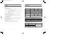
3132A-E/03-08 03.8.6 10:33 AM ページ 6 Continuity Test (Resistance Test) Ranges(IEC 61557-4) Ranges Measuring range to keep Maximum percentage operating error operating error 3Ω 0.2Ω - 3Ω ±30% The influencing variations used for calculating the operating error are denoted as follows: 。 。 Temperature : 0 C and 35 C Supply voltage : 6.4V to 10.4V 。 Position : Reference position ±90 ※Prior to measurement, apply 0-Adjustment at each position.
3132A-E/03-08 03.8.6 10:33 AM ページ 6 Continuity Test (Resistance Test) Ranges(IEC 61557-4) Ranges Measuring range to keep Maximum percentage operating error operating error 3Ω 0.2Ω - 3Ω ±30% The influencing variations used for calculating the operating error are denoted as follows: 。 。 Temperature : 0 C and 35 C Supply voltage : 6.4V to 10.4V 。 Position : Reference position ±90 ※Prior to measurement, apply 0-Adjustment at each position.
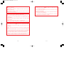
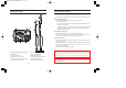
3132A-E/03-08 03.8.6 10:33 AM ページ 8 4.Instrument Layout 5.Preparation for Testing 5-1 Mechanical Zero Adjustment Check that the pointer lines up with the middle of the mark on the scale correctly. If not, adjust it by rotating the meter movement zero adjust with a screwdriver, etc. ⑫ ⑪ 5-2 Battery Voltage Check ⑩ ③ ④ ⑤ ⑧ ⑨ ① Set the range selector switch to BATT. CHECK position. ② Press the test button. ③ Then the pointer deflects. Judge the battery status with BATT.GOOD mark on the scale plate.
3132A-E/03-08 03.8.6 10:33 AM ページ 8 4.Instrument Layout 5.Preparation for Testing 5-1 Mechanical Zero Adjustment Check that the pointer lines up with the middle of the mark on the scale correctly. If not, adjust it by rotating the meter movement zero adjust with a screwdriver, etc. ⑫ ⑪ 5-2 Battery Voltage Check ⑩ ③ ④ ⑤ ⑧ ⑨ ① Set the range selector switch to BATT. CHECK position. ② Press the test button. ③ Then the pointer deflects. Judge the battery status with BATT.GOOD mark on the scale plate.
3132A-E/03-08 03.8.6 10:33 AM ページ 10 6. 6-2 Insulation Resistance Measurement Operation 6-1 AC Voltage Warning Function DANGER ● Never make measurements with the battery compartment cover removed. CAUTION ● Never press the test button if the live circuit warning lamp is lit or the warning buzzer sounds. This may damage the circuit. Voltage check can be made with the range selector switch at any position. ① The presence of AC voltage can be detected.
3132A-E/03-08 03.8.6 10:33 AM ページ 10 6. 6-2 Insulation Resistance Measurement Operation 6-1 AC Voltage Warning Function DANGER ● Never make measurements with the battery compartment cover removed. CAUTION ● Never press the test button if the live circuit warning lamp is lit or the warning buzzer sounds. This may damage the circuit. Voltage check can be made with the range selector switch at any position. ① The presence of AC voltage can be detected.
3132A-E/03-08 03.8.6 10:33 AM ページ 12 ④ Check the circuit under test is not energized as follows. Connect the test probe to the circuit under test and read a voltage value. If the circuit is live, the meter indicates the voltage, the live circuit lamp is lit, and warning buzzer sounds. If the meter indicates 0V, the circuit is dead. ⑤ Press test button. Read the scale directly for the 500V range, multiply by 0.5 for 250V and by 2 for 1000V.
3132A-E/03-08 03.8.6 10:33 AM ページ 12 ④ Check the circuit under test is not energized as follows. Connect the test probe to the circuit under test and read a voltage value. If the circuit is live, the meter indicates the voltage, the live circuit lamp is lit, and warning buzzer sounds. If the meter indicates 0V, the circuit is dead. ⑤ Press test button. Read the scale directly for the 500V range, multiply by 0.5 for 250V and by 2 for 1000V.
3132A-E/03-08 03.8.6 10:33 AM ページ 14 CAUTION ● Never press the test button if the live circuit warning lamp is lit or the warning buzzer sounds. This may damage the circuit. ● In case that an additional operating circuit is connected in parallel to the circuit under measurement, the measurement error might be caused due to the effects of impedance of the circuit connected in parallel or transient current. ① Set the range selector switch to the desired position 3( or 500(.
3132A-E/03-08 03.8.6 10:33 AM ページ 14 CAUTION ● Never press the test button if the live circuit warning lamp is lit or the warning buzzer sounds. This may damage the circuit. ● In case that an additional operating circuit is connected in parallel to the circuit under measurement, the measurement error might be caused due to the effects of impedance of the circuit connected in parallel or transient current. ① Set the range selector switch to the desired position 3( or 500(.
3132A-E/03-08 03.8.6 10:33 AM ページ 16 8.Notes on Accessories 9.Cleaning of the Instrument 8-1 Case Lid ◎ Cleaning the meter cover The case can be fitted under the housing case as illustrated bellow. ① Open the case lid as shown. ② Turn it 180 degrees. ③ Put the case lid under the housing case. This tester is managed by our company's quality standard and is delivered in the best condition after passed the inspection.
3132A-E/03-08 03.8.6 10:33 AM ページ 16 8.Notes on Accessories 9.Cleaning of the Instrument 8-1 Case Lid ◎ Cleaning the meter cover The case can be fitted under the housing case as illustrated bellow. ① Open the case lid as shown. ② Turn it 180 degrees. ③ Put the case lid under the housing case. This tester is managed by our company's quality standard and is delivered in the best condition after passed the inspection.
3132A-E/03-08 03.8.6 10:33 AM ページ 表4 INSTRUCTION MANUAL DISTRIBUTOR Kyoritsu reserves the rights to change specifications or designs described in this manual without notice and without obligations. KYORITSU ELECTRICAL INSTRUMENTS WORKS, LTD. ANALOGUE INSULATION-CONTINUITY TESTER MODEL 3132A No.5-20,Nakane 2-chome, Meguro-ku, Tokyo 152-0031 Japan Phone :(03) 3723-0131 Fax : (03) 3723-0152 URL : http://www.kew-ltd.co.jp E-mail : info@kew-ltd.co.