INSTRUCTION MANUAL DIGITAL PSC-LOOP TESTER MODEL 4116A, 4118A, 4120A KYORITSU ELECTRICAL INSTRUMENTS WORKS,LTD.
CONTENTS 1. SAFE TESTING .............................................................................. 1 2. PROCEDURE OF REMOVING COVER ......................................... 3 3. FEATURES ...................................................................................... 4 3.1 Instrument Layout .................................................................... 4 3.2 Test Lead .................................................................................. 5 3.3 Features .........................
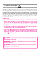
1. SAFE TESTING Electricity is dangerous and can cause injury and death. Always treat it with the greatest of respect and care. If you are not quite sure how to proceed, stop and take advice from a qualified person. This instruction manual contains warnings and safety rules which must be observed by the user to ensure safe operation of the instrument and retain it in safe condition. Therefore, read through these operating instructions before using the instrument. IMPORTANT: 1.
DANGER ● This instrument is intended only for use in single phase operation at 230V +10% -15% AC phase to earth or for use in OLD-TT system phase to neutral. ● When conducting tests do not touch any exposed metalwork associated with the installation. Such metalwork may become live for the duration of the test. ● When testing, always be sure to keep your fingers behind the safety barriers on the test leads. ● Be sure to remove the test lead from the mains power supply promptly after measurement.
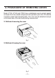
2. PROCEDURE OF REMOVING COVER Model 4116A, 4118A and 4120A have a dedicated cover to protect against an impact from the outside and prevent the operation part, the LCD and the connector socket from becoming dirty. The cover can be detached and put on the back side of the main body during measurement. 2.1 Method of removing the cover Fig. 1 2.2 Method of housing the cover Fig.
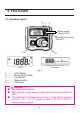
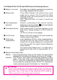
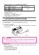
3. FEATURES 3.1 Instrument Layout ⑤ ① ② Wiring correct (Green LED's) Reversed L/N terminals (Red LED) ③ ④ Connector LCD Fig. 3 1............ LCD display 2............ Wiring check LEDs 3........... Test button 4............ Range switch 5............ Connector DANGER ● Use original test lead only. ● Max. allowed voltage between mains test terminals and ground is 300V.
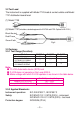
3.2 Test Lead The instrument is supplied with Model 7125 lead at socket outlets and Model 7121 distribution board lead. (1) Model 7125 (2) Model 7121(Included as standard equipment for M-4118A and 4120A. Optional for M-4116A.) Black-Neutral Red-Phase Green-Earth Fig.4 3.3 Features 3.3-1 Test Range (Function): Model D-LOK Circuit * Loop 0-19.99Ω/ 0-199.9Ω/0-1999Ω PSC 0-199.9A/ 0-1999A/0-4.
3.3-3 Model 4116A, 4118A and 4120A have the following features: ● Battery is not used All models are not battery-operated, but operate by the voltage supplied from the system. ● Wiring check Three LEDs indicate if the wiring of the circuit under test is correct. The P-E and P-N LEDs illuminate when the wiring polarity of the circuit under test is correct. The Reverse LED is lit when P and N are reversed.
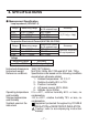
4. SPECIFICATIONS ● Measurement Specification Loop Impedance ( IEC61557-3) Range 20Ω 200Ω 2000Ω Measuring range 0.00∼19.99Ω 0.0 ∼199.9Ω 0 ∼1999Ω Nominal test current at 0Ω external loop 25A / 20ms 2.3A / 40ms 15mA /280ms Accuracy ±(2%rdg + 4dgt) Prospective Short-circuit Current (M-4118A, M-4120A) Nominal test current Range Accuracy Measuring range at 0Ω external loop 2.3A / 40ms 200A 0.0 ∼199.9A Consider accuracy 25A / 20ms 2000A 0 ∼1999A of Loop Impedance 25A / 20ms 20kA 0.00 ∼ 4.
● Operating Error of Loop Impedance (61557-3) Measuring range to keep Maximum percentage operating error operating error 20Ω 0.20 ∼ 19.99Ω 200Ω ±30% 20.0 ∼ 199.9Ω 2000Ω 200 ∼ 1999Ω The influencing variations used for calculating the operating error are denoted as follows: Temperature:0℃ and 40℃ Phase angle :At a phase angle 0゜to 18゜ System frequency:49.5Hz to 50.5Hz System voltage:230V+10%-15% Range 5. OPERATING INSTRUCTIONS 5.1 Initial Checks - To be carried out before any testing.
WARNING ● If the above sequence is NOT displayed or the RED LED is on for any reason , DO NOT PROCEED AS THERE IS INCORRECT WIRING. The cause of the fault must be investigated and rectified. (3) Voltage Measurement When the instrument is first connected to the system, it will display the phase-neutral voltage which is updated every 1s. This mode is cancelled whenever the test button is pressed. If this voltage is not normal or as expected, DO NOT PROCEED.
5.3 Measurement of Prospective Short Circuit Current − (Models 4118A and 4120A) (1) Set the instrument to the 20kA range. (2) Connect the test lead to the instrument. (3) Attach the plug to the socket to be tested. (4) Check that the LED's are lit in the sequence indicated in section 5.1. If not, disconnect from the mains and check the wiring at the socket. (5) Press the "Press to Test" button. The prospective short circuit current (PSC) will be directly displayed on the LCD with the appropriate units.
In the event of a fault, the Fault loop impedance should be low enough (and the Prospective Fault current higher enough) in order to have the automatic disconnection of supply by the installed protection device within prescribed time interval. Every circuit must be tested to make sure that the fault loop impedance does not exceed that specified for the over current protection device concerned.
The figure below shows in marked line the Fault loop impedance for TN system. Fig.7 According to the international Standard IEC 60364 for TT system the following condition shall be fulfilled for each circuit: RA<50/Ia Where: ¡ RA is the sum of the resistances of the local earth system R and protection conductor connecting it to the exposed conductive part.
Practical example of verification of the protection in a TT system according to the international Standard IEC 60364. RCD 30mA RO L1 L2 L3 N PE R Fig.8 For this example max value is 1667Ω, the loop tester reads 12.74Ω, it means that the condition RA<50/Ia is respected. It is fundamental for this example to test also the RCD to ensure that operation takes place quickly enough to respect the safety requirements. In order to do it, can be used the RCD tester model 5406A.
For instance in a TN system with nominal mains voltage Uo = 230 V protected by gG fuses the Ia and max Zs values could be: Rating (A) 6 10 16 20 25 32 40 50 63 80 100 Disconnecting time 5s Disconnecting time 0.4s Ia (A) Zs (Ω) Ia (A) Zs (Ω) 28 8.2 47 4.9 46 5 82 2.8 65 3.6 110 2.1 85 2.7 147 1.56 110 2.1 183 1.25 150 1.53 275 0.83 190 1.21 320 0.72 250 0.92 470 0.49 320 0.71 550 0.42 425 0.54 840 0.27 580 0.39 1020 0.
Max value of Zs for this example is 2.1Ω (16A gG fuse, 0.4s) the loop tester reads 1.14Ω (or 202 A on Fault current range) it means that the condition Zs <Uo/Ia is respected. In fact the Zs of 1.14Ω is less than 2.1Ω (or the Fault current of 202 A is more than Ia of 110A). WARNING ● This instrument is intended only for use in single phase operation at 230V +10% -15% AC phase to earth or for use in OLD-TT system phase to neutral.
WARNING (OLD-TT system only) ● DO NOT PRESS the "Test button" if the display reads a value of 220V! The RCD could trip during the tests also with model 4120A. CAUTION ● The D-LOK circuit of 4120A can not works with 127V between phase to earth. 6.3 Measurement of Line Impedance and Prospective Short Circuit Current Line Impedance on single-phase system is the impedance measured between phase and neutral terminals.
WARNING ● This instrument is intended only for use in single phase operation at 230V +10% -15% AC phase to earth or for use in OLD-TT system phase to neutral. ● If the overheat symbol appears in the display ( ) disconnect the instrument from the mains supply and allow to cool down. ● When testing installation that has a large current capacity, such as a power line, be sure not to short live conductors with the tip of a probe. Failure to follow these instruction can cause hazards to the user. 7.
DISTRIBUTOR 92-1483 01-05 Kyoritsu reserves the rights to change specifications or designs described in this manual without notice and without obligations.