INSTRUCTION MANUAL Leak Logger for Measuring & Recording leakage current KEW LEAK LOGGER MODEL 5000/5001 KYORITSU ELECTRICAL INSTRUMENTS WORKS,LTD.
Contents 1. Safety warnings ............................................................................... 1 2. Features ............................................................................... 3 3. Instrument layout............................................................................... 4 3-1) Panel ............................................................................... 4 3-2) Menu configuration ................................................................... 5 3-3) LCD ..........
1. Safety Warnings This instrument has been designed, manufactured and tested according to IEC 61010: Safety requirements for Electronic Measuring apparatus, and delivered in the best condition after passed the inspection. This instruction manual contains warnings and safety rules which must be observed by the user to ensure safe operation of the instrument and retain it in safe condition. Therefore, read through these operating instructions before using the instrument.
DANGER ¡ Never make measurement on the circuit in which voltage over AC300V exists. ¡ Do not attempt to make measurement in the presence of flammable gasses. Otherwise, the use of the instrument may cause sparking, which can lead to an explosion. ¡ Transformer jaw tips are designed not to short the circuit under test. If equipment under test has exposed conductive parts, however, extra precaution should be taken to minimize the possibility of shorting.
2. Features ¡ This instrument is a leak logger for measuring and recording leakage current. ¡ Capable of recording leakage current from 1 to 3ch with leakage clamp sensor. (Leak clamp sensors: M-8141/8142/8143 are available.) ¡ Can measure and record max. AC1000mA(50/60Hz) with RMS. ¡ LED current indicator flashes when the preset current value is exceeded. (Event/ Max. value/ Capture recording mode) ¡ Can store 60,000 data when using 1ch, and when using all 3ch, can store 20,000 data at each channel.
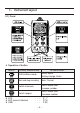
3.Instrument layout 3-1) Panel ¡ Operation of button Button At recording / measurement mode: At menu mode: Shift to Menu mode Select Menu, Setting change, Enter Start and stop recording Back, Cancel Switch channels Switch Menu item, Increase number Switch ranges Switch Menu item, Decrease number ¡ LCD ¡ LED current indicator ¡ USB ・・・ P. 7 ・・・ P.18 ・・・ P.
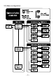
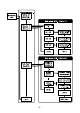
3-2) Menu configuration ―5―
―6―
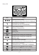
3-1) LCD 100mA 1000mA Mark Details Selected channel number (The measured value at this channel is displayed.) Auto-power-off is disabled. (Instrument won't be off automatically.) Timer function is activated. (Stand-by till the preset time.) Recording Battery mark Recording mode Displayed when viewing the recorded data. Displayed when viewing the recorded max. and min. value. One-time system is activated. (Recording stops when memory becomes full.) Scale function is activated.
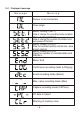
3-4)Displayed message Meaning Message Sensor is not connected. Over-range Menu: Setting1(SET.1) View or change the recording mode/ condition. Menu: Setting2(SET.2) View or change the Location information and auto-power-off function. Menu: Status 1(STS.1) View the recorded quantity and the max. value at each channel. Menu: Status 2(STS.2) View the number of recorded data and RECALL. Menu: End Continuous recording mode (LOGging) Event recording mode (detect) Max.
4.Recording procedures Following explains the flow of operation: through preparation to the stop of recording. P. 10 Step1: Preparation ▼ Select the appropriate sensor, and connect it to the instrument. P. 11 Step2: Confirmation and change of set value ▼ Confirm the recording mode. P. 12 Step3: Preparation before a recording ▼ Install the instrument and do setups for each channel. P. 14 Step4: Start of recording ▼ Start recording. P. 15 Step5: Stop of recording Stop recording.
Step1: Preparation 1. Connect the clamp sensor to the instrument firmly with careful attention to the orientation of the connector. 2. Press the button at least 1 sec. to power on the instrument. Release the button when all indications are displayed on the LCD. 3. Time is displayed on the LCD for 1 sec. If incorrect time is displayed each time when the instrument is powered on, battery for the clock may be exhausted.
Step2: Confirmation and change of set value Confirm the mark indicating the selected recording mode. Refer to "5. Recording modes and conditions" in this manual to change the recording mode or condition (Recording interval/ Preset current value). Recording mode Continuous recording Event recording Max. value Recording Capture recording Details Refer to: Intermittent measured value is recorded continuously at the preset interval. (15-kind: 1 sec. to 60 min.) P.
Step3: Preparation before a recording 1. Clamp on the measured object and fix the Clamp sensor. 㩷 㩷 㩷 2. Instrument shall be firmly fixed so as not to come off easily. 1)Hang the instrument on hook: Can fix the instrument with a hook or screw by using the hooking hole on the top of the instrument. 2)Fix the instrument with magnet on its back. Can fix the instrument to metallic plate with the magnet on its backside. 㩷 3. Press the button to switch the display of measured value among Channel (1) and (3).
4. Press the button to switch the measurement ranges at each channel. The Range hold function is activated when the mark is displayed on the LCD. 㩷 㩷 㩷 Note ¡ At continuous recording mode: It switches in the sequence below. Auto-ranging→1000mA→100.0mA→ Auto-ranging ¡ At Event/ Max. value/ Capture recording mode: It switches between 1000mA and 100.0mA. Range cannot be switched during a recording. Select the appropriate range before a recording. 5.
Step4: Start of recording Follow the procedures stated below and start recording. Be sure to check each setting before starting a recording since the settings cannot be changed during a recording. 㩷 㩷 㩷 㩷 1. Press down the button for a while. ¡ At continuous recording mode or after changing the recording mode; "CLr" flashes while the button is being pressed down. A few seconds later, the measured value and the "REC" mark are displayed on the LCD. Then a recording starts.
Following operations are available during a recording. * Display the measured value at each channel button * Recording state: Display the max. recorded value →Refer to (2) Confirmation of recorded data (status 1) described in the supplied Quick manual. * Recording state: Display RECALL →Refer to (3) Confirmation of recorded data (status 2) described in the supplied Quick manual. * Confirm the setting value at Setting1 "SEt.1" and Setting2 "SEt.2". Following operations are NOT available during a recording.
5. Recording modes and conditions Continuous recording mode: Recording interval of 1min. Max. number of recorded data Using all 3 channels Using 2 channels 20,000 data 40,000 data Max. recording duration Recording interval 1sec. 2sec. 5sec. 10sec. 15sec. 20sec. 30sec. Using only 1 channel 60,000 data Recording Using all 3 channels interval 5:33:20 1min. 13 days/ 21:20:00 11:06:40 2min. 27 days/ 18:40:00 1 day/ 3:46:40 5min. 69 days/ 10:40:00 2 days/ 7:33:20 10min.
㩷 2. Press the button when "SEt.1" is displayed on the LCD. 㩷 㩷 㩷 㩷 3. The selected recording mode is displayed. When (Continuous recording mode) is displayed on the LCD, press the button to proceed to the next setting. In case that , or is displayed on the LCD, press the button. Then the indication on the LCD flashes. Press the or button to change it to . Press the button. 4. The recording interval is displayed. Can be selected from; 1, 2, 5, 10, 15, 20, 30 sec.
㩷 㩷 5. State of One-time system is displayed. on: Recording stops when memory becomes full. off: Overwrite the old data, and store the latest data. button and proceed to ¡ Press the the next step when not changing the setting. ¡ To change the setting, press the button. Then the indication on the LCD flashes. Press the or button to set the value to the desired one. Then press the button to confirm it. 㩷 㩷 6. Now Setting 1 is complete; "End" is displayed on the LCD.
Event recording mode: Current set value of 15mA Max. number of recorded data Using all 3 channels Using 2 channels 1,600 data 2,400 data Using only 1 channel 4,800 data Setting procedure 1. Power on the instrument, and press the button. Then the instrument goes into Menu mode. Each button acts as follows at Menu mode. → :Select, Change, Enter → :Return, Cancel → :Switch, Increase set value → :Switch, Decrease set value 㩷 2. Press the button when "SEt.1" is displayed on the LCD. 㩷 㩷 㩷 3.
㩷 㩷 㩷 㩷 㩷 㩷 4. Pre-set current value at channel 1 is displayed. Can be set at every 1mA from 0 to 1000mA button and proceed to the ¡ Press the next step when not changing the setting. button. ¡ To change the setting, press the Then the indication on the LCD flashes. Press the or button to set the value to the desired one. Then press the button to confirm it.
Max. value recording mode: Current set value of 15mA Max. number of recorded data Using all 3 channels Using 2 channels 330 data 495 data Using only 1 channel 990 data Setting procedure 1. Power on the instrument, and press the button. Then the instrument goes into Menu mode. Each button acts as follows at Menu mode. → :Select, Change, Enter → :Return, Cancel 㩷 → :Switch, Increase set value → :Switch, Decrease set value 2. Press the button when "SEt.1" is displayed on the LCD. 㩷 㩷 㩷 3.
㩷 㩷 㩷 㩷 㩷 4. Pre-set current value on channel 1 is displayed. Can be set at every 1mA from 0 to1000mA. button and proceed to the ¡ Press the next step when not changing the setting. ¡ To change the setting, press the button. Then the indication on the LCD flashes. Press the or button to set the value the desired one). Then press the button to confirm it.
Capture recording mode: Current set value of 15mA Max. number of recorded data Using only 1 channel 345 data Setting procedure 1. Power on the instrument, and press the button. Then the instrument goes into Menu mode. Each button acts as follows at Menu mode. → :Select, Change, Enter → :Return, Cancel 㩷 → :Switch, Increase set value → :Switch, Decrease set value 2. Press the button when "SEt.1" is displayed on the LCD. 㩷 㩷 㩷 3. The selected recording mode is displayed.
㩷 㩷 㩷 㩷 4. Pre-set current value on channel 1 is displayed. Can be set at every 1mA from 0 to 1000mA. button and proceed to the ¡ Press the next step when not changing the setting. ¡ To change the setting, press the button. Then the indication on the LCD flashes. Press the or button to set the value the desired one). Then press the button to confirm it. Note After 1 data is recorded, current will not be detected until current drops to 50% or less of the preset current value.
6. Recording modes List of recording modes Continuous recording Event recording Max. value recording Capture recording Details P.26 P.27 P.28 P.29 To check: Condition, Intermittent leakage Occurrence of leakage Intermittent leakage, Occurrence of leakage Waveform Can record: 60,000 data(1ch) 20,000 data(3ch) 4,800 data(1ch) 1,600 data(3ch) 990 data(1ch) 330 data(3ch) 345 data Recording mode Available CH Recording interval Pre-set current value 3 channels at the same time 15-kind: 1 sec.
(1) Continuous recording mode ¡ Sampling period and RMS calculation The input signal obtained via the connected sensor is sampled (at 50Hz,approx 0.222mS; at 60Hz, approx. 0.185mS) just for 2-cycle (180 data). Then RMS value is calculated by the sampled 180 data. The instrument goes into stand-by mode till next recording interval comes. ¡ Recording The channels to which each sensor is being connected are switched in sequence at recording interval.
(2) Event recording mode ¡ Current detection and RMS calculation Sampling is performed consistently at 1.6ms intervals. Current is detected by comparing the 1/√2 times of the peak value of sine wave and the preset current value. At the same time, RMS is calculated at 100ms based on the sampling data at every 3.3ms.
(3) Max. value recording mode ¡ Current detection and RMS calculation Sampling is performed consistently at 1.6ms intervals. Current is detected by comparing the 1/√2 times of the peak value of sine wave and the preset current value. At the same time, RMS is calculated at 100ms based on the sampling data at every 3.3ms.
(4) Capture recording mode ¡ Current detection and RMS calculation Sampling is performed consistently only at Channel 1 at 1.6ms intervals. Current is detected by comparing the 1/√2 times of the peak value of sine wave and the preset current value. ¡ Recording When the preset current detection value is exceeded (Point A),the instrument records instantaneous values with corresponding time information for 200ms(10 to 12 waveforms) including 50ms prior to and subsequent to the cross over point.
7. Other settings (Setting2) Menu Setting 2: "SEt.2" Setting items 1) Location information Set the location no. to identify the measuring and recording place. 2) Auto-power-off Enable/ Disable the Auto-power-off function. 3) Time Capable of adjusting the time within 00:00 to 23:59. 4) Timer Display and set the timer. 5) Scale The value: measured value multiplied by scale value, is displayed on the LCD. Setting procedure 1. Power on the instrument, and press the button.
㩷 2. Press the button when "SEt.1" is displayed on the LCD. 㩷 㩷 3. Press the button when "SEt.2" is displayed on the LCD. 㩷 㩷 㩷 㩷 4. "Location information": The location no. is displayed. Can be selected between "P.000" and "P.999". button and proceed to ¡ Press the the next step (Auto-power-off) when not changing the setting. ¡ To change the setting, press the button. Then the indication on the LCD flashes. Press the or button to set the value to the desired one.
5. "Auto-power-off": State of Auto-power-off function is displayed. O n : Enables Auto-power-off function. OFF : Disables Auto-power-off function. button and proceed to ¡ Press the the next step (Time) when not changing the setting. ¡ To change the setting, press the button. Then the indication on the LCD flashes. Press the or button to set the value to the desired one. Then press the button to confirm it. mark is displayed on the LCD Note The when the Auto-power-off function is disabled.
㩷 㩷 7. "Timer": State of Timer function is displayed. Can be set within "00:00" to "23:59". button and proceed to ¡ Press the the next step (Scale) when not changing the setting. ¡ To change the setting, press the button. Then the indication on the LCD flashes. Press the or button to set the value to the desired one. Then press the button to confirm it. " button at least 1 sec. Note Press the " after setting. Then the instrument goes into stand-by mode for recording. Recording starts at the preset time.
㩷 9. Scale value at Channel 2 is displayed. button and proceed to the ¡ Press the next step (Scale value at Channel 3) when not changing the setting ¡ To change the setting, press the button. (Refer to the procedure described for Channel 1.) 10. Scale value at Channel 3 is displayed. button and proceed to the ¡ Press the next step when not changing the setting. ¡ To change the setting, press the button. (Refer to the procedure described for Channel 1.) 㩷 11.
8. Data transfer to PC ¡IInstall PC software "KEW LOG Soft" on your PC before using the instrument. Please refer to the instruction manual for "KEW LOG Soft" which shows how to install the software. (The instruction manual for "KEW LOG Soft" is contained in the supplied CD; or click "Start" → "Program" → "KEW" folder. ¡When connecting the logger to PC for the first time, your PC will recognize this new hardware and install the USB driver.
8-2 Preparation for data transmission (1) Power on the instrument, and get the instrument ready for a measurement. (Note: Data cannot be transferred while the instrument is performing a recording.) (2) Start up the PC software: KEW LOG Soft. 8-3 Operation of PC software Refer to the supplied instruction manual for "KEW LOG Soft" and transfer the data to your PC.
9. Battery replacement WARNING ¡In order to avoid electrical shock, remove sensors from the instrument when replacing batteries. CAUTION ¡Do not mix new and old batteries. ¡ Install batteries in the orientation as shown inside the battery compartment, observing correct polarity. When only the leftmost segment of the Battery mark is flashing on the LCD , it means battery voltage is low. Replace the batteries with new ones.
10. Specification ¡Measuring Ranges and Accuracy * Continuous recording mode [RMS] (50/60Hz,Sine wave) Measuring Accuracy when Accuracy Range range combining with sensor of the instrument 100mA 0∼100.0mA 1000mA 0∼1000mA ±1.0%rdg±5dgt ±2.0%rdg±10dgt ±2.0%rdg±6dgt Crest Factor ≦ 2.5 : Sine wave accuracy +2%+5dgt * Event/Max. value/ Capture recording mode [RMS] (50/60Hz,Sine wave) Range Measuring range 100mA 0∼100.0mA 1000mA 0∼1000mA Accuracy of the instrument ±1.
¡ Display ¡ Low battery warning ¡ Overrange indication : Liquid crystal display : Battery mark display(in 4 levels) : "OL" mark appears when exceeding measuring range. (Max. indication 1049counts.) : Power off function operates ¡Auto power off automatically after a switch remains for 3min.
MEMO ― 40 ―
MEMO ― 41 ―
DISTRIBUTOR Kyoritsu reserves the rights to change specifications or designs described in this manual without notice and without obligations. KYORITSU ELECTRICAL INSTRUMENTS WORKS, LTD. No.5-20, Nakane 2― chome, Meguro-ku, Tokyo, 152-0031 Japan Phone: 81―3―3723― 0131 Fax: 81―3―3723― 0152 URL:http://www.kew-ltd.co.jp E-mail:info@kew-ltd.co.