INSTRUCTION MANUAL Current / Voltage Measurement & Recording KEW LOGGER SERIES Current Logger KEW 5010 Current&Voltage Logger KEW 5020
Introduction Thank you for purchasing KEW LOGGER 5010/5020. Follow the procedure below and set time on the instrument before use. 1) Install the KEW LOG SOFT 2 and the USB Driver according to the instructions written in the Install Manual for KEW LOG Soft 2. 2) Run KEW LOG SOFT 2 once install is completed. (Refer to“4. Start “KEW LOG SOFT 2””in the Install Manual.) 3) Confirm that the LOGGER and a PC is firmly connected with a USB Cable and click“Time Synchronizing” .
Contents 1. Safety warnings ………………………………………………………… 1 2. Features ………………………………………………………………… 4 3. Instrument layout ……………………………………………………… 5 3-1) Panel ……………………………………………………………… 5 3-2) LCD ………………………………………………………………… 5 3-3) Displayed message ……………………………………………… 7 3-4) Function of Button ………………………………………………… 8 3-5) Range/ Filter function …………………………………………… 9 4.
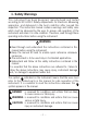
1. Safety Warnings This instrument has been designed, manufactured and tested according to IEC 61010: Safety requirements for Electronic Measuring apparatus, and delivered in the best condition after passed the inspection. This instruction manual contains warnings and safety rules which must be observed by the user to ensure safe operation of the instrument and retain it in safe condition. Therefore, read through these operating instructions before using the instrument.
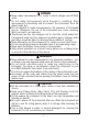
DANGER Never make measurement on a circuit in which voltage over AC300V exists. Do not make measurement while thunder is rumbling. Stop measurement immediately and disconnect the instrument from the object under test. Do not attempt to make measurement in the presence of flammable gasses. Otherwise, the use of the instrument may cause sparking, which can lead to an explosion. Transformer jaw tips are designed not to short the circuit under test.
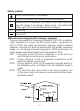
Safety symbols Refer to the instructions in the manual. Indicates a Instrument with double or reinforced insulation Indicates that this instrument can clamp on live bare conductors when the voltage to be tested is below Circuit – Ground-to-Earth voltage against the indicated Measurement Category.
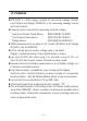
2. Features KEW 5020 is a Data Logger capable of measuring Leakage Current, Load Current and Voltage. (KEW5010 is for measuring Leakage Current and Load Current). Following sensors are used for measuring current & voltage.
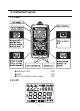
3. Instrument layout 3-1) Panel ◆ Detection LEDs ◆ USB ◆ Port for External power supply 3-2) LCD ̶5̶ P.28 P.43 P.
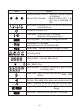
Mark Details Channel number (CH No.) : Selected Channel number is displayed. Memory Block Number : Memory block (No. 1 to 3) in use is indicated. (P. 38) Sensor Mark : Displayed on the CH No. to Indicate the connected Sensor. Clock Mark : Indicates time Timer Mark : Timer function is activated. (Stand-by till the preset time.) Recording Mark : Recording is being performed. Auto-power-off is disabled. (Instrument won't be off automatically.
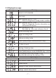
3-3) Displayed message Message Meaning Sensor is not connected. Over-range Menu: Setting1 (SET.1) P.18 View or change the recording mode/ condition. Menu: Setting2 (SET.2) P.34 View or change the Location information and auto-power-off function. Menu: Recall(CALL) P.39 Recorded qty.
3-4) Function of Button Power ON / OFF Button Power ON Pressing at least 1 sec (while the LOGGER is off) Power OFF Pressing at least 1 sec (except for recording status) Recording/ Measurement mode Button Function Enter into Menu mode Start and stop recording Switch channels Switch Range and Filter (P.
3-5) Range/ Filter Function ●Range Configuration Range configuration varies depending on each connected Sensor. Refer to "12. Specification" (P.45) in this manual. ●Auto-ranging Auto-ranging is available only in Normal Recording mode. It isn't available on a Sensor providing one single range. (e.g. Voltage Sensor "KEW8309" for KEW5020) ●Range Hold Select the ranges with mark to fix measurement range under Normal Recording mode.
4. Recording procedures Following explains the flow of operation: through preparation to the stop of recording. P.11 Step1: Start-up ▼ P.12 Select the appropriate sensor, and connect it to the instrument. Step2: Confirmation of the set value P.13 ▼ Confirm the recording mode. Step3: Preparation before recording ▼ P.15 Install the instrument and do setups for each channel. Step4: Start of recoding P.17 ▼ Start recording. Step5: Stop of recording Stop recording.
Step1: Start-up ▼ ▼ 1. Press the button and power off the instrument. Connect a Clamp/ Voltage Sensor to CH1 (for multiple connection, starting from CH1) while the instrument is being off. Connect them firmly with careful attention to the orientation of the connector. 2. Press the button at least 1 sec. to power on the instrument. Release the button when all indications are displayed on the LCD. First, time is displayed, and then sensors being connected are displayed.
4. Can make measurement right after powering on the instrument. * Each time pressing the button, CH1 to CH3 switches. When (non-connect) is displayed on the LCD, a sensor is not connected to the selected channel; or the connection is incorrect. Step2: Confirmation of preset value Check the mark indicating the selected recording mode. Refer to“5.
Step3: Preparation before recording 1. Clamp on the measured object and fix the Sensor. Firmly fix it so as not to easily come off. Care should be taken, when connecting the Voltage Sensor designed only for KEW5020, not to short the object under test. ▼ 2. Fix the instrument. 1) Fix the instrument with magnet : Can fix the instrument to metallic plate with the magnet on its backside.
4. Check a Range/ Filter Press the button to check their on/off status. Press the button to change them. Independent setting of Range & Filter is available on each CH. Point ●At Normal Recording mode, Range and Filter switches each time pressing the button. Auto-ranging is also available. ●At Trigger/Capture/Power Quality Analysis modes, only Filter on/off is available. Range is selected automatically based on the detection level (preset value for Trigger/ Capture Recording). See Setting1 "SEt.1".
Step3: Preparation before recording * Settings cannot be changed during recording. Carefully check the settings prior to a recording. * Previous recorded data is cleared and new recording starts when changing the followings and starts recording. (In this case, "CLr" flashes on the LCD at a start of recording.) 1) Recording mode is changed. 2) CH for Sensor is changed. 3) Sensor type is changed. * Transfer important data to your PC first and clear Memory (P.
Memory Block ◆One memory block is used from the start to the end of recording. ◆3 blocks in the Memory Block are available; it enables 3 different recordings at different locations. ◆Transfer important data to your PC first and clear Memory (Setting 2 or via PC) since further recording isn't activated when all the 3 blocks in Memory Block are used. ◆Settable Location No. at Setting 2 "SEt.
Step5: Stop of recording In case that One-time is set to "ON" at Step2: Confirmation and change of preset value, recording is stopped automatically when Memory becomes full. 1. Press the button at least 1 sec to stop recording. 2. Recording stops, and the " " mark disappears. Then the instrument goes back into measurement state. Now, recording completes. button at least 1 sec to power off the instrument. * Press the * It is recommended to transfer the important data to a PC.
5. Recording modes and conditions * Recording mode and condition can be set on the instrument ; but PC software "KEW LOG Soft 2" provides much easier setting. * Only Normal and Trigger Recording modes can be set on the instrument. Capture recording and Power Quality Analysis modes need to be set via a PC. (Recording condition for the Capture Recording mode is changeable on the instrument.) ●Setting on the instrument (Menu Mode) 1. Power on the instrument, and press the button to enter into Menu Mode. 2.
Normal recording mode: Recording interval of 1min. Max. number of recorded data Using all 3 channels 20,000 data Using 2 channels Using only 1 channel 30,000 data 60,000 data Max. recording duration Recording Using all 3 channels Using 2 channels Using only 1 channel interval 1 sec. 5:33:20 8:20:00 16:40:00 2 sec. 11:06:40 16:40:00 1 day / 9:20:00 5 sec. 1 day / 3:46:40 1 day /17:40:00 3 days/11:20:00 10 sec. 2 days/ 7:33:20 3 days/11:20:00 6 days/22:40:00 15 sec.
Setting procedure 1. Power on the instrument, and press the button. Then the instrument enters into Menu mode. ▼ 2. Press the button when "SEt.1" is displayed on the LCD. ▼ ▼ 3. Selected recording mode is displayed. ◆When (Normal recording mode) is displayed on the LCD, press the button to proceed to the next setting. ◆In case that , or is displayed on the LCD, press the button. Then the indication on the LCD flashes. Press the or button to change it to . Press the button.
4. Then recording interval is displayed. Can be selected from; 1, 2, 5, 10, 15, 20, 30 sec., 1, 2, 5, 10, 15, 20, 30, 60 min ▼ ◆Press the button and proceed to the next step when not changing the setting. ◆To change the setting, press the button. Then the indication on the LCD flashes. Press the or button to set the value to the desired one. Then press the button to confirm it. 5. Next, One-time/ Endless is indicated. One-time: Recording stops when memory becomes full.
Trigger recording mode: Current set value of 15A Max. number of recorded data Using all 3 channels 1,600 data Using 2 channels 2,400 data Using only 1 channel 4,800 data Setting items Item CH1 Detection Level CH2 Detection Level CH3 Detection Level One-time/ Endless Setting procedure ▼ Range for Setting 0 ~ 1000 (Unit depends on Sensor) 0 ~ 1000 (Unit depends on Sensor) 0 ~ 1000 (Unit depends on Sensor) One-time/ Endless Default 15 15 15 Endless 1. Connect a Sensor first prior to do setting.
5. Detection level at CH1 is indicated. Can be set at every 1 from 0 to 1000 ◆To change the setting, press the button. Then the indication on the LCD flashes. ◆Press the or button to set the value to the desired one. Then press the button to confirm it.
8. Now Setting 1 is completed; "End" is displayed on the LCD. Press the button to return to the screen on which "SEt.1" is displayed. 9. Press the button to get the instrument ready for a measurement. Capture recording mode:(Setting on PC) * Setting is available only on PC.
6. Recording modes List of recording modes Normal Recording Trigger Recording Capture recording Power QualityAnalysis P.29 P.30 Detection of abnormal voltage variation(only 5020) Recoding mode Details P.26 P.27 Detection of abnormal current/ voltage 60,000 data (1ch) 4,800 (1ch) Can record: 20,000 data (3ch) 1,600 data data (3ch) Status/ Application Simplified power monitor Check of waveform 345 data Available CH 3 channels at the same time Recording 15-kind: 1 sec. to Interval 60 min.
1. Normal Recording mode ●Sampling period and RMS calculation Sampling the inputs at every 1.6ms/CH and calculate the measured value (RMS) at every 100ms. The Peak value (crest value in sampling data) will be updated and kept. ●Recording Average of the measured value is recorded at every recording interval. RMS measured values, Max, Min and Peak values (sampled crest value converted to sine RMS value) are recorded at every 10 times of recording.
2. Trigger Recording mode ●Detection and RMS value calculation Sampling the inputs at every 1.6ms and comparing the Peak value (sampled crest value converted to sine RMS value) and Detection level. For current, when the Peak value exceeds the level and for voltage when the Peak value is below the level; detection is triggered. RMS value is calculated at every 100ms. ●Recording When the Detection level is exceeded, 8 data (for about 0.
◆Flashing Detection LED ●LED on the Sensor connected channel blinks when following Trigger is detected. Trigger is detected when the measured values exceed the pre-set detection level under Trigger/ Capture Recording Mode. Trigger is detected when the measured current values exceed the pre-set detection level under Trigger/ Capture Recording Mode and Power Quality Analysis Mode. For voltage values, Trigger is detected when it is below the detection level.
3. Capture Recording mode ●Detection and RMS value calculation Sampling the inputs at every 0.55ms only at CH1 and comparing the Peak value (sampled crest value converted to sine RMS value) and Detection level. For current, when the Peak value exceeds the level and for voltage when the Peak value is below the level; detection is triggered. RMS value is calculated at every 100ms.
4. Power Quality Analysis Mode (only 5020) ●Detection and RMS value calculation Sampling the inputs at every 0.55ms only at CH1 and comparing the Peak value (sampled crest value converted to sine RMS value) at every 10ms and preset value to detect swell, dip and short interruption in power supply. RMS value is calculated at every 100ms. ●Recording When swell, dip or short interruption is detected, the detected value is recorded as Start (S) with time and date information.
7. Simplified Power Integration (available via KEW LOG Soft 2) The PC software "KEW LOG Soft 2" provides easy calculation of integral power consumption by use of current and voltage (only on KEW5020) recorded under Normal Recording mode. ●On KEW 5010, measures and records current values, and then enter any voltage value and power factor on "KEW LOG Soft 2" to calculate simplified power consumption.
◆Single-phase 3-wire (1Φ3W) L1 N SOURCE L2 LOAD V Model Name KEW 5010 KEW 5020 A1 CH1 CH2 CH3 A1 A1 V A2 A2 A1 ----A2 A2 KEW LOG Soft2 Fixed parameters Voltage value, Power factor Voltage value, Power factor Power factor ◆Three-phase 3-wire (3Φ3W) SURCE L1 L2 L3 LOAD V A1 A2 General formula is: P=V×(A1×cos(30° +Φ2)), -Φ1)+A2×cos(30° however, here Φ1=Φ2 is applied.
◆Three-phase 4-wire (3Φ4W) Model Name KEW 5010 KEW 5020 CH1 CH2 CH3 A1 A1 A2 A2 A3 A3 KEW LOG Soft2 Fixed parameters Voltage value, Power factor Voltage value, Power factor * Refer to "KEW LOG Soft 2- HELP" how to operate KEW LOG Soft 2. The latest "KEW LOG Soft 2" can be downloaded from our web site. http://www.kew-ltd.co.
8. Other settings (Setting2) ●Recording mode and condition can be set on the instrument; but PC software "KEW LOG Soft 2" provides much easier setting. ●Time setting for Year, Month, Day, Hour, Minute and Second is available on PC, but setting for Hour and Minute only are available on the instrument. Menu Setting 2: "SEt.2" Setting items 1) Location information [Default:000] Set the location no. to identify the measuring and recording place.
Setting procedure 1. Power on the instrument, and press the button. ▼ 2. Press the on the LCD. button when "SEt.1" is displayed 3. Press the on the LCD. button when "SEt.2" is displayed ▼ ▼ 4. "Location information": Location No. is displayed on the LCD. Can be selected between "P.000" and "P.999". ◆Press the button and proceed to the next step (Auto-power-off) when not changing the setting. ◆To change the setting, press the button. Then the indication on the LCD flashes.
additional recordings (up to 3 Memory Blocks), it is recommended to set each Location No. in advance. It is useful to identify the recorded locations per Memory Block. ●Location No. is linked to the Location list and allows to display the Location name, which corresponding to the Location No., when displaying data on PC Software. ●I n c a s e o f s e t t i n g L o c a t i o n n o . o n t h e instrument, it is recommended to take notes of the Location No. and the name. ▼ ▼ 5.
6. "Time": Time is displayed. Can be adjusted between "00:00" and "23:59". ◆Press the button and proceed to the next step (Timer) when not changing the setting. ◆To change the setting, press the button. Then the indication on the LCD flashes. Press the or button to set the value to the desired one. Then press the button to confirm it. Point Connect the instrument to PC and set time and date via PC software : "KEW LOG Soft 2". ▼ 7. "Timer": State of Timer function is displayed.
8. "Memory Clear": Clear the recorded data. ◆Press the button to end Setting 2 when you don't clear the Memory. ◆P re s s i n g t h e button flashes the indication on the LCD. Recorded data isn't deleted by pressing the button, while "no" is displayed on the LCD. Press the button to change the indication to "CLr", and then press the button to clear the recorded data. Message "O DATA" is indicated and back to "CLr" indication when data is cleared. ▼ 9.
9. Confirmation of recorded data (CALL) Details of data in the present Memory Block can be viewed during recording and when recording is completed. ◆Display of percentage of recorded data against memory capacity. ◆Capable of checking max, min, instant Peak/ Detection value at each channel with time & date information. ◆RECALL: can check the latest 10 data with time and date information. Each button acts as follows at Menu mode.
3. Press the on the LCD. Button while "CALL" is displayed ▼ 4. Check of Percentage of recorded data against memory capacity is displayed. * Memory block with recorded data is indicated by the Marks: ❶❷❸. When all 3 marks are lit up, all the Memory blocks are used. Transfer the important data to a PC and clear the Memory to perform next recording. Pressing the next. Button proceeds to the ▼ 5.
6. Display of the number of the recorded data at CH2/ the number of detected current & voltage data in case of Trigger Recording mode. Pressing the Button moves to CH3. ◆ Press the Button to check max, min and peak values with time and date information. See P.42 <>. ▼ 7. Display of the number of the recorded data at CH3/ the number of detected current & voltage data in case of Trigger Recording Mode. Pressing the Button moves to "RECALL".
<> * Pressing the Button changes the information about the selected channel in following sequence. MAX「Mon.Day'Year」→「Time:Min'Sec"」→「Max」→MIN 「Mon.Day'Year」 →「Time:Min'Sec"」 →「Min」 → 「Mon.Day'Year」 → Instant Peak/Detected value 「Time:Min'Sec"」 →「Instant Peak/Detected value」 ◆Indication of「- - - -」stands for no data at the selected channel. ◆Pressing the Button returns to the window with "Number of data".
10. Data transfer to PC ●Install PC software "KEW LOG Soft 2" on your PC to enable data communication between the instrument and your PC. Refer to the HELP contained in "KEW LOG Soft 2" which shows how to install the software. It will be on the Desktop after installing the software, or found in the folder of "KEW" from "Start" → "Program". ●When connecting the logger to PC for the first time, your PC will recognize this new hardware and install the USB driver.
10-2 Preparation for data transmission (1) Power on the instrument, and get the instrument ready for a measurement. (Note: Data cannot be transferred while the instrument is performing a recording.) (2) Start up the PC software: KEW LOG Soft 2. 10-3 Operation of PC software Refer to the supplied instruction manual for "KEW LOG Soft 2" or "Help" and transfer the data to your PC.
11. Battery replacement WARNING In order to avoid electrical shock, remove sensors from the instrument when replacing batteries. CAUTION Do not mix new and old batteries. Install batteries in the orientation as shown inside the battery compartment, observing correct polarity. is flashing When only the leftmost segment of the Battery mark on the LCD, it means battery voltage is low. Replace the batteries with new ones. There is no influence on the measurement accuracy even if this warning mark is flashing.
12. Auto-power off Function & External Power Supply 1) Auto-power off Function LOGGER is automatically powered off in about 3 min after the last key operation while Auto-power off Function is "ON" at Setting 2. This mark)although function doesn't work during recording (LCD with readings aren't displayed on the LCD due to Power-saving Function. In case of using an external power supply for making measurement, disable the Auto-power off Function. Then long period measurement is possible.
13. Troubleshooting When defect or breakdown of the instrument is suspected, check the following points first. If your problem isn't listed in this section, contact your local Kyoritsu distributor. Symptom / Check 1. Unable to measure.( is displayed.) Check if a sensor is connected to the properly. Insert the sensor into the connector terminal firmly. KEW 5010 doesn't recognize the voltage Sensor 2. Unable to measure. ( is displayed.
7. When the logger is connected to the PC using the USB cable, the logger connected is not detected in the logger list. Check if the USB cable is connected correctly. Check if the USB driver is installed. Check if the USB driver is failed to be installed on the PC. If the installation is failed, firstly delete the USB driver installed and re-install it according to the procedure stated in the USB Notice sheet or Install Manual. 8.
14. Specification Measuring Range and Accuracy (AC 50/60Hz,Sine wave, Input: 10% or more of the range at CH1) KEW 8146 (30A) :100.0mA/1000mA/10.00A/30.0A KEW 8147 (70A) :100.0mA/1000mA/10.00A/70.0A KEW 8148 (100A) :100.0mA/1000mA/10.00A/100.0A Range KEW 8121 (100A) :10.00/100.0A KEW 8122 (500A) :50.00/500.0A KEW 8123 (1000A) :100.0/1000A KEW 8309 (600V) :600.
Operating system : Successive Approximation (CH1 single synchronized sampling) Rated max. working voltage : AC9.9Vrms, 14V peak value Number of input channel : 3ch Measuring method : True RMS RMS measuring interval : approx. 100ms. Sampling interval Normal/Trigger mode : approx. 1.65ms/CH Capture mode : approx. 0.55ms (waveform: at every 1.1ms) P.Q.A mode : approx. 0.
Dimension Weight Accessories Option : 111(H) x 60(W) x 42(D)mm : Approx.265g : Alkaline battery LR6 x 4pcs PC software "KEW LOG Soft 2”: 1pce USB cable: 1pce.
memo ̶ 52 ̶
DISTRIBUTOR Kyoritsu reserves the rights to change specifications or designs described in this manual without notice and without obligations.