INSTRUCTION MANUAL MULTI-FUNCTION TESTER KEW 6010B KYORITSU ELECTRICAL INSTRUMENTS WORKS,LTD.
CONTENTS 1.Safe Testing.................................................................................... 1 2.Instrument Layout........................................................................... 3 3.Features.......................................................................................... 4 4.Specification................................................................................... 6 5.Continuity (resistance) tests...........................................................
1. SAFE TESTING (READ BEFORE USING) Electricity is dangerous and can cause injury and death. To avoid possible electric shock, personal injury or damage of instrument, always treat it with the greatest of respect and care. If you are not quite sure how to proceed, stop and take advice from a qualified person. 1. 2. 3. 4. 5. 6. 7. 8. 9. 10. 11. 12. 13. This instrument must only be used by a competent and trained person and operated in strict accordance with the instructions.
returned to your distributor for attention. 14. Do not operate the function switch while the instrument is connected to a circuit. If, for example, the instrument has just completed a continuity test and an insulation test is to follow, disconnect the test leads from the circuit before moving the function switch. 15. Do not rotate function switch when test button is depressed.
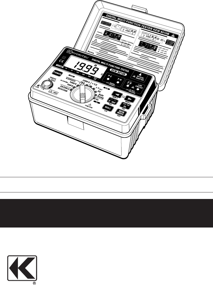
2. INSTRUMENT LAYOUT Fig.1 IΔn SELECT SWITCH: Available FUNCTION NO.6, 7, 8, 9, 10 (MEMORY SELECT SWITCH) 0° /180° SELECT SWITCH: Available FUNCTION NO.4, 6, 7, 8, 9 (MEMORY RECALL SWITCH) UL VALUE SELECT SWITCH: Available FUNCTION NO.6, 7, 8, 9 (ENTER SWITCH) AUTO NULL SWITCH: Available FUNCTION NO.1 (MEMORY CLEAR SWITCH) MEMORY MODE SWITCH (MEMORY MODE EXIT SWITCH) The switch name shown in ( ) is used in MEMORY MODE.
3. FEATURES KEW 6010B Multi-Function tester performs six functions in one instrument. 1. Continuity tester 2. Insulation resistance tester (500V/1000V) 3. Loop impedance tester 4. RCD tester 5. Uc tester 6. Mains voltage warning when operating the Loop, RCD and Uc mode. Above test results: item1 through 5, can be saved to the internal memory; and they can be recalled whenever necessary. Data can be transferred from KEW6010B to PC by using MODEL8212 and "KEW Report" (Optional accessory).
Wiring check Over temperature protection 15mA Loop measurement DC Test Phase angle selector UL(touch voltage limit) value change and Uc monitoring Other features:Auto data hold Auto power off Data memory Indication Optional Accessory Three LEDs indicate if the wiring of the circuit under test is correct.
4.
Voltage Measurement Rated Voltage (AC) Measuring Range (AC) 100-250V 50Hz 100-300V Accuracy 3% rdg @ Loop/RCD/Uc Range To prevent wrong connection of test leads and to maintain safety, the dedicated terminals used for continuity and insulation tests are automatically covered when using the terminals for Loop impedance, RCD and Uc tests. Typical Number of Tests (central tendency for supply voltage up to 8V at R6P) Continuity Ranges : Approx. 700 times min.
● Operating Error of RCD (IEC 61557-6) Function ×1/2 ×1, FAST Auto Ramp Operating error of trip current -10% - 0% 0% -+10% -10% -+10% The influencing variations used for calculating the operating error are denoted as follows: Temperature : 0℃ and 35℃ Earth electrode Resistance (shall not exceed below) : IΔn (mA) 10 30 100 300 500 Earth electrode resistance (Ωmax.) UL25V UL50V 2000 2000 600 600 200 200 65 130 40 80 System voltage : 230V+10%-15% Supply voltage : 8V to 13.
LED indication of live circuit warning LED indication of correct polarity Display Overload protection Mains Voltage Indication Illuminates if there is an alternating voltage of 20V AC or more in the circuit under test before Continuity or Insulation resistance tests. When DC voltage is detected across the measuring terminal the LED lights up. The P-E and P-N LEDs illuminate when the wiring of the circuit under test is correct. The reverse LED " " is lit when P and N are reversed.
5. CONTINUITY (RESISTANCE) TESTS WARNING ENSURE THAT CIRCUITS TO BE TESTED ARE NOT LIVE. DISCONNECT THE INSTRUMENT FROM THE CIRCUIT UNDER TEST BEFORE OPERATING THE FUNCTION SWITCH. TO SELECT THE LOW RESISTANCE RANGE SELECT "CONTINUITY" 5.1 Test Procedure The object of continuity testing is to measure only the resistance of the parts of the wiring system under test.
4.Release the test button. Press the test button and ensure the display reads zero before proceeding. While using the Continuity null function, " " appears on the LCD. The null value will be stored even if power off the instrument. The memorized null value can be cancelled by disconnecting the test leads and pushing the AUTO NULL SWITCH with the test button pressed or locked. CAUTION-before taking any measurements always check the leads have been zeroed.
6. INSULATION TESTS WARNING ENSURE THAT CIRCUITS TO BE TESTED ARE NOT LIVE. DISCONNECT THE INSTRUMENT FROM THE CIRCUIT UNDER TEST BEFORE OPERATING THE FUNCTION SWITCH.
6.1.3 Conduction Current Since the insulation resistance is not infinite, a small leakage current flows through the insulation between conductors. Since Ohm's Law applies, the leakage current can be calculated from applied voltage (V) Leakage current (µA) = insulation resistance (MΩ) Fig 5 6.1.4 Surface Leakage Current Where insulation is removed, for the connection of conductors and so on, current will flow across the surfaces of the insulation between the bare conductors.
quickly falling to zero so that it has no effect on the measurement. A high voltage is used because this will often break down poor insulation and cause flashover due to surface leakage (see 6.1.4), thus showing up potential faults which would not be present at lower levels. The insulation tester measures the applied voltage level and the leakage current through the insulation.
6.3 Preparation for measurement Before testing, always check the following:1. The low battery Indication " " is not displayed 2. There is no visually obvious damage to the tester or to the test leads. 3. Test the continuity of the test leads by switching to continuity test and shorting out the lead ends. A high reading will indicate that there is a faulty lead or that the fuse is blown. 4. MAKE SURE THAT THE CIRCUIT TO BE TESTED IS NOT LIVE.
3.If the mains warning LED lights and/or the buzzer sounds DO NOT PRESS THE TEST BUTTON but disconnect the instrument from the circuit. Make the circuit dead before proceeding. Fig 8 4. Press the test button when the display will show the insulation resistance of the circuit or the appliance to which the instrument is connected. 5. Note that if the circuit resistance is greater than 20MΩ the instrument will automatically range to the 200MΩ reading. 6.
7. LOOP IMPEDANCE TESTS DISCONNECT THE INSTRUMENT FROM THE CIRCUIT UNDER TEST BEFORE OPERATING THE FUNCTION SWITCH TO SELECT THE LOOP TESTING RANGE SELECT“LOOP” 7.1 Voltage Measurement Power on the instrument. When the tester is set to the Loop test function, mains voltage is displayed as soon as the instrument is connected for test. This voltage display is automatically updated every 1 second. 7.
● Impedance of the power transformer secondary winding. ● Impedance of the phase conductor resistance from the power transformer to the location of the fault. ● Impedance of the protective conductor from the fault location to the local earth system. ● Resistance of the local earth system (R). ● Resistance of the power transformer earth system (Ro).
7.4 The loop impedance test Since the earth fault loop is made up of conducting path which includes the supply system back to the supply transformer, it follows that loop testing can only be carried out after the mains supply has been connected. KEW 6010B takes a current from the supply and measures the difference between the unloaded and loaded supply voltages. From this difference it is possible to calculate the loop resistance.
WARNING Do not connect phase to phase as this instrument is rated at 230V. 7.5 Loop impedance at 3 phase equipment Use the same procedure as in 7.4 above ensuring that only one phase is connected at a time i.e.: First Test: red lead to phase 1, black lead to neutral, green lead to earth. Second Test: red lead to phase 2, black lead to neutral, green lead to earth etc. WARNING NEVER CONNECT THE INSTRUMENT TO TWO PHASES AT THE SAME TIME. Testing as described in 7.4 and 7.
Fig 12 8. RCD/Uc TESTS DISCONNECT THE INSTRUMENT FROM THE CIRCUIT UNDER TEST BEFORE OPERATING THE FUNCTION SWITCH TO SELECT THE RCD OR UC TEST RANGE SELECT "RCD" OR "UC" 8.1 Purpose of the RCD test The RCD must be tested to ensure that operation takes place quickly enough to ensure that there is unlikely to be serious danger to a person experiencing an electric shock from the system.
8.3 What is Uc? Ground being imperfect in the Fig13, when R exists, when a fault current flows to R, electric potential occurs. There is a possibility the person contacting in this imperfect ground, it calls the voltage, which it occurs in the human body of this time, called Uc. When with the Uc Test letting flow IΔN to the RCD, the Uc is calculated. Fig 13 Uc voltage is calculated based on the Rated Residual Current (IΔN) with the impedance measured.
8.4 Uc Testing 1.Power on the instrument and set the function switch to "Uc". 2.Set the IΔN to the rated residual operating current of the RCD under test. 4.Connect the instrument to the RCD to be tested either via a suitable socket outlet (see Fig 11) or using the Model 7133 (OMA DIEC) test lead set (see Fig 12). 5.Make sure that the P-E and P-N wiring check LEDs are lit and the wiring incorrect LED is not lit. If they are not, disconnect the tester and check the wiring for a possible fault.
3.Set the phase angle to indicate 0° in the display. (The initial value is 0° ) 4.Set the UL value 50V or 25V. (The initial value is 50V) 5.Connect the instrument to the RCD to be tested either via a suitable socket outlet (see Fig 11) or using the Model 7133 (OMA DIEC) test lead set (see Fig 12). 6.Make sure that the P-E and P-N wiring check LEDs are lit and the wiring incorrect LED is not lit. If they are not, disconnect the tester and check the wiring for a possible fault.
8.6.2 "FAST TRIP" Test RCDs rated at 30 mA or less are sometimes used to provide extra protection against electric shock. Such RCDs require a special test procedure as follows:1.Set the function switch to "X1 FAST" and the IΔN select switch to "FAST 150". 2.Set the phase angle to indicate 0° in the display. 3.Connect the instrument to the RCD to be tested. 4.Make sure that the P-E and P-N wiring check LEDs are lit. If they are not, disconnect the tester and check the wiring for a possible fault.
8.7 Testing time delayed RCDs RCDs with a built-in time delay are used to ensure discrimination, that is, that the correct RCD operates first. Testing is carried out in accordance with item 8.6 above, except that the displayed tripping times are likely to be longer than those for a normal RCD. Since the maximum test time is longer, there may be danger if earthed metal is touched during the test. MAKE SURE TO KEEP CLEAR OF EARTHED METAL DURING THE OPERATION OF THIS TEST.
9. STORE / RECALL A MEASURED RESULT Measured result at each function can be stored in the memory of the instrument. (MAX : 300) When KEW 6010B is in MEMORY MODE, " " is being displayed on the LCD. 9.1 How to store the data Store the result according to following sequence. STORE (1) Measured result (2) Press to enter into MEMORY MODE. (" " appears on the LCD.) (3) Press or (000 - 299) (4) Press Undo and select Data No. . (Confirmed) Undo (5) Press or and select Place No. (P.00 - P.99) (6) Press .
9.2 Recall the stored data Stored data can be displayed on LCD according to following sequence. (1) Press to enter into MEMORY MODE (" " appears on LCD). NORMAL MODE MEMORY MODE (2) Press to recall. Undo (3) Press or and select Data No.(000 - 299) (4) Press . Can check the followings. Measured result Undo Function No. (See Fig 1) Place No. Note: By pressing MEMORY MODE SWITCH during an operation, can also undo the last action or release MEMORY MODE.
9.3 Delete the stored data Stored data can be deleted according to following sequence. (1) Press to enter into MEMORY MODE (" " appears on LCD). NORMAL MODE MEMORY MODE (2) Press to recall. Undo (3) Press or and select Data No. ("ALL" ← → 000 - 299 ← → "ALL") (4) Press . "clr" is displayed and blinking or Delete (5) Press Press Not delete , the data is deleted with beep. , the data is not deleted. After either operation, returns to Data No.
9.4 Transfer the stored data to PC The stored data can be transferred to PC via Optical Adapter Model 8212 (Optional Accessory). ●How to transfer the data: (1) Firmly insert the D-SUB 9Pin female connector of Model 8212 into the socket (D-SUB 9Pin male) of PC. (2) Insert Model 8212 into KEW 6010B as shown in Fig 14. Test Leads shall be removed from KEW 6010B at this time. (3) Power on KEW 6010B. (Any function is OK.) (4) Start special software "KEW Report" on your PC and set the communication port.
10. BATTERY / FUSE REPLACEMENT WARNING NEVR OPEN THE BATTERY COVER WHILE MAKING MEASUREMENT. TO AVOID POSSIBLE ELECTRICAL SHOCK, DISCONNECT THE TEST LEAD AND POWER OFF THE INSTRUMENT BEFORE OPENING THE BATTERY COVER FOR BATTERY OR FUSE REPLACEMENT. 10.1 Battery replacement When the display shows the low battery indication " ", disconnect the test leads from the instrument and power off. Remove the battery cover and the batteries. Replace with eight (8) new 1.
11. GENERAL The test button can be locked down for ease of use by pressing it and turning clockwise. Do not forget to release test button by turning it counterclockwise before disconnecting the instrument from the test points. Failure to do so may leave the tested circuit in a charged condition when carrying out insulation test.
13. CASE, STRAP AND SHOULDER-PAD ASSEMBLY Correct assembly is shown in Fig 16. By hanging the instrument round the neck, both hands will be left free for testing. ① Pass the strap DOWN through the first case lug,under the case and UP through the other lug. ② Side the sholder-pad onto the strap. ④ Pass the strap through the buckle,adjust the strap for length and secure. ③ Feed the strap DOWN through the slots in the back of the test-lead pouch.
DISTRIBUTOR 92-1733 05-02 Kyoritsu reserves the rights to change specifications or designs described in this manual without notice and without obligations.