INSTRUCTION MANUAL MULTI-FUNCTION TESTER MODEL 6011A KYORITSU ELECTRICAL INSTRUMENTS WORKS,LTD.
CONTENTS 1.Safe Testing.................................................................................... 1 2.Features.......................................................................................... 3 3.Specification................................................................................... 6 4.Continuity (resistance) tests........................................................... 10 4. 1 Instrument layout...................................................................
1. SAFE TESTING Electricity is dangerous and can cause injury and death. Always treat it with the greatest of respect and care. If you are not quite sure how to proceed, stop and take advice from a qualified person. 1.This instrument must only be used by a competent and trained person and operated in strict accordance with the instructions. KYORITSU will not accept liability for any damage or injury caused by misuse or non-compliance with the instructions or with the safety procedures.
barriers on the test leads. 11.During testing it is possible that there may be a momentary degradation of the reading due to the presence of excessive transients or discharges on the electrical system under test. Should this be observed, the test must be repeated to obtain a correct reading. If in doubt, contact your distributor. 12.The sliding shutter on the back of the instrument is a safety device.
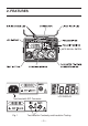
2. FEATURES MΩ AUTO NULL/Uc SWITCH Test Lead with IEC Connector Fig.
Model 6011A Multi-Function tester performs six functions in one instrument. 1.Continuity tester 2.Insulation resistance tester 3.Loop impedance tester 4.Prospective short circuit current tester 5.RCD tester 6.Mains voltage warning when operating the loop impedance and RCD mode. The tester is designed to Safety Standard IEC 61010-1 CAT III (300V). Drip-proof construction in conformance with IP54, IEC 60529. The instrument is supplied with:1.A KAMP10 lead for loop/RCD testing at socket outlets.
Over temperature protection 15mA Loop measurement DC Test Auto data hold Auto power off UL value change and UC Monitoring Optional Accessory Detects overheating of the internal resistor (used for loop and PSC tests) and of the current control MOS FET (used for RCD tests) displaying a warning symbol ( ) and automatically halting further measurements. Loop impedance200Ω and 2000Ωrange measurement are carried out with low test current (15mA).
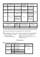
3. SPECIFICATION Measurement Specification Function Open Circuit Voltage (DC) Continuity Greater than 6 V Short Circuit Current Greater than 200mA Range Accuracy 20/200/2000Ω ± (1.5%rdg + 3dgt) Auto- Ranging Accuracy of this instrument will be affected on the continuity range if used in proximity of radio transmitters Open Circuit Voltage (DC) Rated Current Range Accuracy 250V+40%−0% 1mA or greater @ 250kΩ 20/200 MΩ Auto-Ranging ± (1.
Function Rated Voltage (AC) Trip Current Duration Trip Current Accuracy Trip Current: -10% +0% of range at 230V Trip Current: 2000ms 230V+10%-15% 10/30/100/300/ RCD X 1 +10% -0% of 500/1000 mA 1000mA@200ms range at 230V Trip Time 50Hz ±(1% rdg Trip Current: 10 mA ± 10% of + 3dgt) range at 230V 230V+10%-15% 30/100/300mA 50ms RCD X 5 (Note:on × 5 50Hz Trip Current: range maximum +10% -0% of current that can range at 230V be generated is 1A) RCD X 1/2 230V+10%-15% 10/30/100/300/ 50Hz 500/1000 mA 2000ms
The influencing variations used for calculating the operating error are denoted as follows; Temperature: 0 ℃and 35 ℃ Supply voltage : 8V to 13.8V ● Operating error of Loop Impedance(IEC61557-3) Range Measuring range to keep operating error 20Ω 200Ω 2000Ω 0.4 ~ 19.99Ω 20.0 ~ 199.
Battery type Low battery warning 5.DC power source: 12.0 V, ripple content 1% or less 6. Altitude up to 2000m Eight R6 or LR6 batteries. " " symbol appears in the display and the buzzer beeps if the battery voltage drops below 8V. Operating temperature and humidity. Storage temperature and humidity 0 to +40:, relative humidity 80% or less, no condensation. -20 to +60℃, relative humidity 75% or less, no condensation.
4. CONTINUITY(RESISTANCE)TESTS WARNING ENSURE THAT CIRCUITS TO BE TESTED ARE NOT LIVE. DISCONNECT THE INSTRUMENT FROM THE CIRCUIT UNDER TEST BEFORE OPERATING THE FUNCTION SWITCH. TO SELECT THE LOW RESISTANCE RANGE SELECT“CONTINUITY” 4.1 Instrument layout See Fig 1. 4.2 Test Procedure The object of continuity testing is to measure only the resistance of the parts of the wiring system under test. This measurement should not include the resistance of any test leads used.
turned to the OFF position. The memorized null value can be cancelled by disconnecting the test leads and pushing the AUTO NULL/Uc SWITCH with the test button pressed or locked. CAUTION-before taking any measurements always check the leads have been zeroed. 5.Connect the test leads to the circuit whose resistance is required (see Fig 3 for a typical connection arrangement). Having first made sure that the circuit is not live.
5. INSULATION TESTS WARNING ENSURE THAT CIRCUITS TO BE TESTED ARE NOT LIVE. DISCONNECT THE INSTRUMENT FROM THE CIRCUIT UNDER TEST BEFORE OPERATING THE FUNCTION SWITCH.
Fig 4 5.1.3 Conduction Current Since the insulation resistance is not infinite, a small leakage current flows through the insulation between conductors. Since Ohm's Law applies, the leakage current can be calculated from Leakage current (µA) = applied voltage (V) insulation resistance (MΩ) Fig 5 5.1.4 Surface Leakage Current Where insulation is removed, for the connection of conductors and so on, current will flow across the surfaces of the insulation between the bare conductors.
5.1.5 Total Leakage Current The total leakage current is the sum of the capacitive, conduction and surface leakage current described above. Each of the currents, and hence the total leakage current, is affected by factors such as ambient temperature, conductor temperature, humidity and the applied voltage. If the circuit has alternating voltage applied, the capacitive current (5.1.2) will always be present and can never be eliminated.
¡ ¡ ¡ ¡ ¡ ¡ ¡ ¡ ¡ ¡ ¡ Electronic fluorescent starter switches Passive infra-red detectors (PIRs) Dimmer switches Touch switches Delay timers Power controllers Emergency lighting units Electronic RCDs Computers and printers Electronic point-of-sale terminals (cash registers) Any other device which includes electronic components.
Fig 7 Note:Insulation testing must only be undertaken on de-energised circuits. 3.If the mains warning lamp lights and/or the buzzer sounds DO NOT PRESS THE TEST BUTTON but disconnect the instrument from the circuit. Make the circuit dead before proceeding. Fig 8 4.Press the test button when the display will show the insulation resistance of the circuit or the appliance to which the instrument is connected.
6.When testing is complete release the test button BEFORE disconnecting the test leads from the circuit or from the appliance. This will ensure that the charge built up by the circuit or the appliance during insulation test is dissipated in the discharge circuit. In the discharging process, an LED illuminates and the live circuit warning buzzer will sound. CAUTION NEVER TURN THE FUNCTION DIAL WHILE THE TEST BUTTON IS DEPRESSED AS THIS MAY DAMAGE THE INSTRUMENT.
6. LOOP IMPEDANCE TESTS DISCONNECT THE INSTRUMENT FROM THE CIRCUIT UNDER TEST BEFORE OPERATING THE FUNCTION SWITCH TO SELECT THE LOOP TESTING RANGE SELECT“LOOP” 6.1 Voltage Measurement When the tester is set to the loop test function, mains voltage is displayed as soon as the instrument is connected for test. This voltage display is automatically updated every 1 second. The voltage function operates whenever the test button is in the up position. 6.
6.4 The loop impedance test WARNING DO NOT PROCEED WITH TESTING UNLESS THE P-E AND P-N LAMPS ARE LIT TO CONFIRM THAT THE WIRING IS CORRECTLY CONNECTED. Should these two lamps not be lit, investigate the wiring connections of the installation and rectify any faults before proceeding with the test. If the LED is lit do not proceed. a. Loop Impedance at Mains Socket Outlet 1.Select the 20Ω,200Ωor 2000Ωrange as desired 2.Connect the mains lead to the IEC socket of the instrument(see fig9).
6.5 Loop impedance at 3 phase equipment In order to test the Loop impedance at 3 phase equipment the optional OMA DIEC(Model7133) is necessary. Use the same procedure as in 6.4 above ensuring that only one phase is connected at a time i.e.:First Test: red prod to phase 1, black prod to neutral, green crocodile clip to earth. Second Test: red prod to phase 2, black prod to neutral, green crocodile clip to earth etc. WARNING:N EVE R C O N N E C T TH E I NSTR U M E NT TO TWO PHASES AT THE SAME TIME.
BLACK NEUTRAL RED PHASE GREEN EARTH Fig 10 7. PROSPECTIVE SHORT CIRCUIT CURRENT(PSC)TESTS WARNING NEVER CONNECT THIS INSTRUMENT ACROSS 2 PHASES. N EVE R AT TE M PT TO M EAS U R E TH E P HAS E TO P HAS E PROSPECTIVE SHORT CIRCUIT CURRENT. 7.
1.Select the 200A, 2000A or 20kA range. 2.Connect the OMA DIEC(Model7133) distribution board lead to the IEC socket on the instrument. 3.Connect the red phase probe of the OMA DIEC(Model7133) to the phase of the system, the black probe to the neutral of the system and the green crocodile clip to the neutral of the system. 4.Carry out the initial checks. 5.Press the test button. A bleep will sound as the test is conducted and the value of PSC will be displayed.
8.2 What does the RCD test really do? The RCD is designed to trip out when the difference between the phase current and the neutral current (this is called the residual current) reaches the tripping value (or rating) of the device. The tester provides a carefully preset value of residual current depending on its setting and then measures the time lapse between the application of the current and the operation of the RCD. 8.
4.Connect the instrument to the RCD to be tested either via a suitable socket outlet(see fig 9)or using the OMA DIEC(Model7133) test lead set(see fig 10). 5.Make sure that the P-E and P-N wiring check lamps are lit and the wiring incorrect LED is not lit. If they are not, disconnect the tester and check the wiring for a possible fault. 6.If the lamps are correctly lit, press the test button to apply half the rated tripping current for 2000 ms, when the RCD should not trip.
display. 6.Press the phase selector switch to indicate 180™in the display and repeat the test. 7.MAKE SURE TO KEEP CLEAR OF EARTHED METAL DURING THE OPERATION OF THIS TEST. 8.7 Testing time delayed RCDs RCDs with a built-in time delay are used to ensure discrimination, that is, that the correct RCD operates first. Testing is carried out in accordance with item 8.3 above, except that the displayed tripping times are likely to be longer than those for a normal RCD.
9. The external earth terminal .The external earth terminal at the ranges of Loop, PSC and RCD, the buzzer warns that the mains earth is switched to the external earth terminal. Connect the external earth probe firmly to a new earth point and press the test button to measure loop impedance. If the connection of the external earth probe and the terminal is normal, the move of symbols is repeated on the LCD, and finally, the measured value is displayed. LCD Display when the external earth terminal is used.
10. GENERAL The test button can be locked down for ease of use by pressing it and turning clockwise. Do not forget to release test button by turning it counterclockwise before disconnecting the instrument from the test points. Failure to do so may leave the tested circuit in a charged condition when carrying out insulation test.
If the instrument will not operate in the loop impedance, PSC and RCD modes, it may be that the protective fuses fitted on the printed circuit board have blown. If you suspect that the fuses have failed, return the instrument to your distributor for service - do not attempt to replace the fuses yourself. SPARE FUSE SCREW FUSE BATTERY Fig 12 13. SERVICING If this tester should fail to operate correctly, return it to your distributor stating the exact nature of the fault.
14. CASE AND STRAP ASSEMBLY Correct assembly is shown in Fig 12. By hanging the instrument round the neck, both hands will be left free for testing.
DISTRIBUTOR 92-1530D 05-02 Kyoritsu reserves the rights to change specifications or designs described in this manual without notice and without obligations.