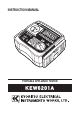
INSTRUCTION MANUAL PORTABLE APPLIANCE TESTER KEW6201A
CONTENTS 1. Safe testing ………………………………………………………………………………………1 2. Procedure of removing cover ……………………………………………………………. 3 2.1 Method of removing the cover ……………………………………………………. 3 2.2 Method of storing the cover ………………………………………………………. 3 3. Product summary and explanation ……………………………………………………. 3.1 Product summary …………………………………………………………………….. 3.2 Test range ………………………………………………………………………………… 3.3 Features …………………………………………………………………………………... 3.4 Instrument layout …………………………………………………………………….. 3.
1. Safe testing Electricity is dangerous and can cause injury and death. Always treat it with the greatest of respect and care. If you are not quite sure how to proceed, stop a measurement and take advice from a qualified person. This instruction manual contains warning and safety rules which must be observed by the user to ensure safe operation of the instrument and retain it in safe condition. Therefore, read through these operating instructions before using the instrument.
# DANGER • This instrument can be connected only to the commercial power of 240V+10%-10%, 50Hz. • For safety reasons, only use the Test Leads designed to be used with this instrument and recommended by KYORITSU. • Use only grounded mains outlets to supply the instrument. Do not touch the device under test while testing is in progress. • Since a high voltage of 500V is outputting continuously, especially while measuring insulation resistance, user may get electrical shock.
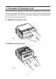
2. Procedure of removing cover KEW 6201A have a dedicated cover to protect against an impact from the outside and prevent the operation part, the LCD, and the connector socket from becoming dirty. The cover can be detached and put on the back side of the main body during measurement. 2.1 Method of removing the cover Fig. 1 2.2 Method of storing the cover Fig.
3. Product summary and explanation 3.1 Product summary The KEW 6201A is a hand-held portable appliance tester, performing four functions to ensure the Safety of Class I and Class II appliances. And also can measure the mains voltage. Readings are displayed on a large liquid crystal display (LCD) below which are three LEDs, light up in 2 color, 2 color LEDs which unambiguously display a pass or fail indication for results dictated by international standards.
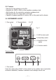
3.3 Features • Warning for the appliance to be ON. • Selection for 250V or 500V on the insulation resistance test. • Null function for the protective conductor resistance test. • Warning for the over range value in the LCD. • Capable of judging pass/fail of tests by LED on the panel and by buzzer. 3.4 INSTRUMENTS LAYOUT ⑴ Test socket ⑵ Terminal block ⑹ LCD Fig.
⑵ Terminal block Connect the attached mains cord and Test Leads to this terminal block. ⑶ Terminal for mains cord This terminal is connected to a mains supply via M7123. ⑷ Terminal for Extension leads adaptor It corresponds to L, N, E of test socket, and the extension leads adaptor (M-7140) connected with the cord reel to be plugged to it.
⑿ Fuse Protected by a fuse of 600V/10A ceramic fuse (F type Φ6.3x32mm). User can replace this fuse. ⒀ Mains cord (AU) M-7123 This mains cord can be connected to the mains supply so that the instrument can derive power from it. To measure contact current, the socket of the main power supply is to be equipped with an earth terminal. Fig. 4 ⒁ Test Lead with safety alligator clip(M-7129A) and Probe with Blade type Prod(M-7161A).
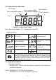
3.5 Explanation for indications LCD Display Null indication Power supply voltage Over temperature warning (Line-Neutral) indication Unit indication Fig. 7 Insulation measurement voltage Note) Over range display:“OL”is displayed on the LCD. Display symbols DUT is OFF. Represents LN-E. When leakage current test is interrupted. Represents leakage current. Represents Protective conductor resistance During the DUT is operated at the leakage current test. Represents the test is fail.
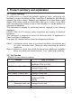
4. Specification 4.1 General specification, measuring range and accuracy Voltage(VOLT) measurement of main power supply Measuring range Resolution Accuracy 207 ~ 264V AC 1V ± (2%rdg+3dgt) Measurement of Protective conductor resistance(RPE) Measuring range Resolution Open-circuit voltage Measuring current Accuracy 0 ~ 15.
4.3 Reference test condition Unless otherwise specified, this specification is dependent on following condition.
5. Preparation before a measurement 5.1 Visual inspection Before starting a measurement, user should undertake visual checks on the mains cord, case and that the correct type and rated fuse is fitted to the DUT. And also there should be no evidence of damage of a nature that may impair the electrical safety of the item. 5.2 Connection to main power supply 5.2.1 Connection of mains cord Set the Function switch to VOLT Function, and connect the mains supply and the instrument with M7123 mains cord. Fig.
# WARNING • When the voltage of main power supply is 265V or more,“HI-V”is displayed on the LCD. • In that case, disconnect the mains cord of the instrument from main power supply. 5.2.3 Null setting A criteria of judgment for Earth Continuity is 1Ω, and it is low value. So even the resistance of Test Leads will affect the measurement result. This instrument, M-6201A, can cancel the resistance of Test lead by pressing Null|250V/500V switch. The procedure of Null setting is shown below.
Press Null|250V/500V switch with contacting the Test Lead and the metal parts, the resistance of Test Lead will be displayed on the LCD as shown above fig.10 for 2sec. Then, the instrument cancels the resistance value of Test Lead and adjust the displayed value to“0.00”as shown below fig.10. At this bout, NULL mark is displayed in the LCD. Null setting cannot be done when a resistance is 3Ω or more. A message“no”appears to indicate a resistance is exceeding the Null setting range.
6. Measuring method 6.1 Class I Test The purpose of the test carried out for Class I appliances is to check the insulation resistance between accessible conductive parts and connection of protective earth and between live wire parts and accessible conductive parts is within the range defined in the standards. To conduct the tests of protective conductor resistance and insulation resistance for DUT, connect the mains plug of DUT to the test socket (1) described in clause 3.4.
Class I Test Flowchart Start ⑴. Protective conductor resistance. No RPE < = 1Ω? Light up in red “no”→ “Con” →“value”will be repeated on the LCD. Yes Light up in green ⑵.Appliance switch test Is the Switch turning on? No Yes When the resistance between LN is about 100kΩ or more “no”→ “OFF”is displayed alternately on the LCD. (3). Insulation resistance between L/N and PE. LnE > = 1MΩ? No Light up in red “no”→ “LnE”→“value”will be repeated on the LCD. Yes Light up in green PASS Value (1). and (3).
6.2 Class I Test (Select the Leakage current test) Selecting“Class I test”while Select Switch is being pressed down initiates Leakage current test instead of Insulation resistance test. In case of selecting Leakage current test, metal parts other than the heating or movable parts must be clipped with Test Lead M-7129A since the DUT activates. Pressing the START/STOP switch during Leakage current test stops the test immediately.
# CAUTION • When the terminal is open or the resistance value exceeds measuring range,“OL”mark (over range display) appears on the LCD. • The test will stop. A message“Stp”appears on the LCD but values of Leakage current aren't displayed. # WARNING • Operate a device and measure the leakage current flowing on it at Leakage current test function. Care should be taken not to touch with the heating or movable parts during tests. Extra care should also be taken to light and heat generated by the device.
Class II Test Flowchart Start (1). Appliance switch test No Is the Switch turning on? Yes When the resistance between LN is about 100kΩ or more “no”→ “OFF”is displayed alternately on the LCD. Light up in green (2). Insulation resistance between L/N and PE. No LnE > = 1MΩ? Light up in red “no”→ “LnE”→“value”will be repeated on the LCD. Yes Light up in green PASS Value of (2). will be displayed on the LCD.
Class II Test (Select the Leakage current test) Flowchart Start Power on Leakage current test. 5sec 10sec Brief indications“S-”and“on”will be displayed in turns on the LCD for 5 sec and prompt the user to set the DUT switch on. Then a mark indicating working DUT function will be displayed for 10 sec. LEA < = 1mA ? No Light up in red Stop the test and “no”→ “LEA”→“value”will be repeated on the LCD. Yes Light up in green PASS Value will be displayed on the LCD.
6.5 Extension Leads Test • This test is for extension leads, and check: • Protective conductor resistance between accessible conductive parts and connection of protective earth. • Insulation resistance between L/N and PE. • Polarity check of the Line and Neutral terminal of plug and socket. Test procedure and the connection are as follows. Fig.
Extension Leads Test Flowchart Start (1). Protective conductor resistance test. RPE < = 1Ω? No Light up in red “no”→ “Con” →“value”will be repeated on the LCD. Yes Light up in green (2). Insulation resistance test between L/N and PE. LnE > = 1MΩ? No Light up in red “no”→ “LnE”→“value”will be repeated on the LCD. Yes Light up in green (3). Polarity test between L-L and N-N. L-L & N-N < = 10Ω? No Yes PASS Value of (1) and (2) will be alternately displayed on LCD.
• When the function is set to extension leads test while pressing Select switch, Power on leakage current test will be carried out instead of Insulation resistance test. ・Protective conductor resistance between accessible conductive parts and connection of protective earth. ・Leakage Current test: Measure a leakage current by actually operating the appliance. Extension Leads Test (Select the Leakage current test) Flowchart Start (1). Protective conductor resistance test.
# WARNING • Operate a device and measure the leakage current flowing on it at Leakage current test function. Care should be taken not to touch with the heating or movable parts during tests. Extra care should also be taken to light and heat generated by the device. • Firmly insert the plugs of DUT to the AU socket of this instrument. Plugs may be heated if Leakage current test is performed with improper connection. • Do not connect/remove the plugs during Leakage current test. It may cause reading error.
# WARNING • Operate a device and measure the leakage current flowing on it at Leakage current test function. Care should be taken not to touch with the heating or movable parts during tests. Extra care should also be taken to light and heat generated by the device. • Firmly insert the plugs of DUT to the AU socket of this instrument. Plugs may be heated if Leakage current test is performed with improper connection. • Do not connect/remove the plugs during Leakage current test. It may cause reading error.
# WARNING • Be sure to remove mains cord from the instrument before replacing fuse. • The fuse that user can replace is this fuse only. Never attempt to perform the other repairing. # CAUTION • Please use the specified fuse (Fast acting type ceramic fuse: 600V/10A - Φ6.3x32mm). • For the specified fuse, purchase it by yourself or order it from our agency. 8. Services If this instrument should fail to operate correctly, return it to your distributor.
DISTRIBUTOR Kyoritsu reserves the rights to change specifications or designs described in this manual without notice and without obligations.