
Instruction Manual User Manual


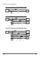
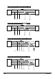

5.1 KEW6305
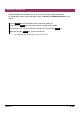
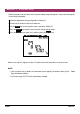
Arrow mark: Points
towards load side.
5. Wiring configurations
5.1 Important Preliminary checks
DANGER
● Do not make measurements on a circuit in which the electrical potential exceeds AC600V.
● Connect the Power cord to a socket outlet. Never connect it to the socket outlet of AC240V or
more.
● The Clamp sensor, Voltage test leads and Power cord are to be connected to the instrument
first.
● The Voltage test leads or Clamp sensors should not be connected to the input terminals of the
instrument if not required for measurement.
● The instrument should always be connected on the downstream side of a circuit breaker, which
is safer than the upstream side.
● Do not open-circuit the secondary side of a supplementary CT while it is energized because of
the high voltage generated at the secondary side terminals.
● Be careful to avoid short-circuiting the power line with the un-insulated part of the voltage test
probes during the setting up of the instrument. Transformer jaw tips are designed in such a way
to avoid short-circuiting. If the circuit under test has exposed conductive parts, extra care should
be taken to minimize the possibility of shorting.
WARNING
● To avoid possible electric shock and short-circuit, always turn off the line under test when setting
up the instrument.
● Do not touch the un-insulated tip of Voltage test probes. The use of safety insulted gloves is
recommended.
● Clamp sensor direction for correct measurement:
Ensure that the arrow mark on the clamp sensor points towards to load side.