
Instruction Manual User Manual

KEW6305 5.6
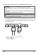
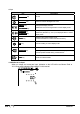
Move the cursor on the line showing an error, and press the ENTER Key. Then the suspected error
value will be displayed on the LCD.
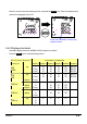
5.4.2 Displayed contents
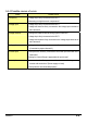
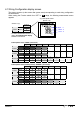
Selectable display screens at WIRING CHECK range are as follows.
Press the Cursor keys to switch following screens.
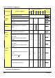
Parameters to be displayed
Wiring system
(Setting 01)
Displayed
at
Screen 1 Screen 2 Screen 3 Screen 4 Screen 5 Screen 6
Top f V1 A1 P1 PF1 DEG(V1)
Middle V(avg) V2 A2 P2 PF2 DEG(V2)
3P4W
3P3W3A
Bottom A(avg) V3 A3 P3 PF3 DEG(V3)
Top f V1 A1 P1 PF1 DEG(V1)
Middle V(avg) V2 A2 P2 PF2 DEG(V2)
3P3W
1P3W
Bottom A(avg) - - - - -
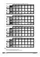
Top f V1 A1 P1 PF1
Middle V1 - A2 P2 PF2
1P2W(3ch)
Bottom A(avg) - A3 P3 PF3
-
Top f V1 A1 P1 PF1
Middle V1 - A2 P2 PF2
1P2W(2ch)
Bottom A(avg) - - - -
-
Top f V1 A1 P1 PF1
Middle V1 - - - -
1P2W(1ch)
Bottom A1 - - - -
-
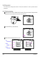
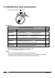
In this case, orientation of sensor (A3)
may be incorrect.