
Instruction Manual User Manual


KEW6305 7.8
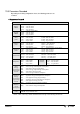
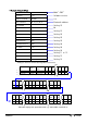
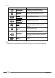
● Indications on each wiring configuration
The following messages are displayed on the screen according to each wiring configuration.
Displayed contents
Wiring(“Setting 01”) Displayed at
Screen1 Screen2 Screen3 Screen4
Upper TIME
Middle WP
1P2W (1ch)
Lower WS
- - -
Upper TIME TIME TIME
Middle WP WP1 WP2
1P2W (2ch)
1P3W
3P3W
Lower WS WS1 WS2
-
Upper TIME TIME TIME TIME
Middle WP WP1 WP2 WP3
1P2W (3ch)
3P3W3A
3P4W
Lower WS WS1 WS2 WS3
Legend:
TIME : Elapsed time of integration
WP : Total active electrical energy
WP1/WP2/WP3 : Active electrical energy per phase
WS : Total apparent electrical energy
WS1/WS2/WS3 : Apparent electrical energy per phase
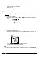
7.5 Saving data
When integration or demand measurement starts, the measured data will be saved automatically.
There are two locations where data can be saved.
* SD card : Max. 511 files can be saved.
* Internal memory : Max. 4 files can be saved.
Data is saved to a SD card automatically when a SD card has been inserted before turning on the
instrument. If the SD card has not been inserted, data is saved automatically to internal memory.
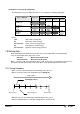
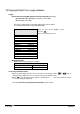
7.5.1 Saving Procedure
* When a survey is started (manually or automatically) a file is opened.
* Data is saved at the end of each integration interval (“Setting 09”).
Elapsed time
Recording interval
1 2 3 n-1 n
Start of survey Data saving point End of survey
* When the survey is closed (manually or automatically) the file is closed
* All the recorded parameters at each data saving point are saved to one file.