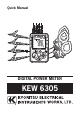
Quick Manual DIGITAL POWER METER KEW 6305
Preface KEW6305 ● Preface This Quick manual is a simplified version of the full instruction manual which can be found in the supplied CD-ROM. This manual is intended only as a handy reference guide and should only be used after having read the full instruction manual which contains full details on each function of this instrument and the items contained in the package.
KEW6305 Instrument Overview 1. Instrument Overview Features This is a digital Power meter that can be used for various wiring systems and can measure up to 3 systems on single-phase 2-wire circuit. That is, this instrument does the jobs of three just by one. It can be used for measurements of instantaneous, integration and also demand values. Measured data can be saved in SD card or the internal memory, and the data can be transmitted to PC via USB.
Functional Overview KEW6305 Functional Overview SET UP Configures KEW6305 and makes settings for measurements. WIRING CHECK Performs a check for proper connection. See (Section 10) “Wiring check” for further details. [W] Instantaneous value measurement Measures average, max, min values of instantaneous values of current, voltage and electric power. See (Section 6) “Instantaneous value measurement” for further details.
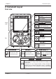
KEW6305 Instrument Layout 2. Instrument Layout Front view Status indicator LED Green Light up: Recording& Measuring Blink: Stand-by Red Light up: Recording error START/ STOP Key Display (LCD) START /STOP Start/stop integration & demand measurements Backlight Key Turn on/off the LCD backlight Cursor Key Select settings, switch screens Keys ENTER Key ENTER Function Switch Power on/ off, select Measurement range.
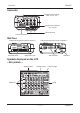
Connector KEW6305 Connector Voltage Input Terminal (VN, V1, V2, V3) Current Input Terminal (A1, A2, A3) Terminal Cover Power Connector Side face < When the Connector Cover is opened > < When the Connector Cover is closed > SD Memory Card SD Card Cover SD Card Slot USB Port Cover USB Port Symbols displayed on the LCD < All symbols > Wiring system Voltage range Current range Units Phase No.
KEW6305 Symbols displayed on the LCD < Symbols appear to show the state of the instrument or measurement > Symbol Description Keys are being locked. Preset voltage value is exceeded. Preset current value is exceeded. Operating with AC power supply. Operating with batteries. Data hold function is active. SET UP Range is selected. WIRING CHECK Range is selected. Blinks while instantaneous value is being displayed on the LCD. Blinks while integration value is being displayed on the LCD.
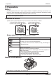
Preparations KEW6305 3. Preparations Battery KEW6305 operates either an AC power supply or batteries. Capable of performing measurements in an event of AC power interruption, power to the instrument is automatically restored by the batteries installed in the instrument. Size AA alkaline dry-cell batteries (LR6) can be used. If an AC power supply is interrupted and batteries have not been installed, the instrument will be powered off and the measuring data may be lost.
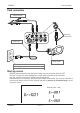
KEW6305 Cord connection Cord connection Voltage test lead Match the arrow marks. Power cord Clamp sensor Rated supply voltage : 100 - 240VAC(±10%) Rated supply frequency : 45 - 65Hz Max power consumption : 10VAmax Start-up screen KEW6305 will be powered on when setting the Function switch to any position other than OFF. All of the LCD segments will be displayed first, and then model name with version information. After that, stand-by screen for the selected range will be displayed.
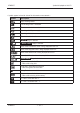
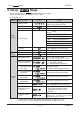
Set-up: SET UP Range KEW6305 4. Set-up: SET UP Range Set the Function switch to SET UP Range for making various settings. Settings listed below can be changed. (27 items in total) List of setting items Setting Setting no.
Set-up: SET UP Range KEW6305 Setting Setting no./ item 18 Available space in SD card SD card/ 19 SD card Format Internal 20 Available space in memory Internal memory 21 I n t e r n a l m e m o r y Format 22 System reset 23 ID number 24 Setting read Others 25 Setting save 26 Bluetooth 27 V / A R a n g e A u t o switching KEW6305 Symbol Details Show the available space in the installed SD card in percentage. ON(Format)/ OFF(Not format) Show the available space in the internal memory in percentage.
Setting procedure KEW6305 4-1. Setting procedure STEP1 Set the Function Switch to SET UP Range. (to show the Set-up screen) Item no. Set-up screen STEP2 STEP3 Use the Cursor keys and switch the Setting items with Setting no. 01 to 27. (Up) (Right) for increasing numbers, (Down) Press on the desired Setting no.. (Left) for decreasing numbers. (corresponding setting item starts blinking and enters into the setting change mode.) STEP4 Use the Cursor keys and change settings.
KEW6305 Wiring system 4-2.
Measurement Ranges KEW6305 5. Measurement Ranges KEW6305 can perform the following three different measurements. (a) Instantaneous value measurement (W Range) (b) Integration value measurement (Wh Range) (c) Demand measurement (DEMAND Range) Select a desirable Range according to the steps below. 1. Set the Function Switch to W/ Wh/ DEMAND Range. Set the switch to W/ Wh/ DEMAND position. 2. Select a Range Any one of following symbols blinks on the LCD to show which Range has been selected. e.g.
Instantaneous value Measurement: W Range KEW6305 6. Instantaneous value Measurement: W Range 6-1.
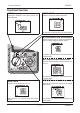
Selecting/switching display contents KEW6305 6-2. Selecting/switching display contents Three parameters (max) can be displayed in one screen. (In the example 1-A below, V, A and P are displayed.) Display screen will be different depending on wiring systems. ● e.g.
KEW6305 Selecting/ switching display contents ● For the other wiring systems: Screens can be switched in the same way as described in the previous page.
Data saving KEW6305 6-3. Data saving Instantaneous values ( W Range) can be saved by manual operation only. [Saving procedure] (1) File no. screen is displayed and data will be saved when pressing the at W Range. Screen at W Range File no. screen Key during a measurement Screen at W Range File no. Key saves another data in the preceding file. (2) Another press of (In this case, File no. is not displayed but the buzzer sounds like“pi”.
Integration value measurement: Wh Range KEW6305 7. Integration value Measurement: Wh Range 7-1. Steps for measurement Ensuring your safety ↓ Preparation for measurement ↓ Setting ↓ Wiring SET UP Range Basic Setting Measurement setting “Setting 01”Wiring system“Setting 09”Recording interval “Setting 02”Voltage range “Setting 10”Specifying rec. period or endless rec.
How to start/ stop measurement KEW6305 7-2. How to start/ stop measurement ● To start/ stop measurement manually Hold down the START /STOP Key for ● To start/ stop measurement at the preset date&time Configure the settings for“Setting 10/ Wh Range over 2 sec. 11/12”, and then press the Key. START /STOP File no. screen is displayed for about 2 sec. - Manual operation : Pressing the START /STOP Key starts measurement anytime.
KEW6305 How to switch screens/ save data 7-3. How to switch screens/ save data ● Screens and switching method < e.g.
Demand Measurement : DEMAND Range KEW6305 8. Demand Measurement : DEMAND Range 8-1. Steps for measurement SET UP Range Basic Setting Measurement setting “Setting 01”Wiring system“Setting 09”Recording interval “Setting 02”Voltage range “Setting 10”Specifying rec. period or endless rec.
KEW6305 How to start/ stop measurement 8-2. How to start/ stop measurement ● To start/ stop measurement manually Hold down the START /STOP Key for ● To start/ stop measurement at the preset date&time Configure the settings for“Setting DEMAND 14/15”, and then press the Range over 2 sec. START /STOP Key. File no. screen is displayed for about 2 sec. - Manual operation : Pressing the START /STOP Key starts measurement anytime.
Screens/ saving data KEW6305 8-3. Screens/ saving data ● Parameters displayed on screens and switching method Screen 1 Top : Target value Middle : Predicted value Bottom : Present value Screen 2 Top : Demand time Middle : Load factor Bottom : Present value Screen 3 Top : Date when max. demand value measured Middle : Time when max. demand value measured Bottom : Max. demand value ● Saving data (Data will be saved automatically.
KEW6305 SD card/ Saved data 9. SD card/ Saved data 9-1. SD card compatibility This instrument supports 1/ 2Gbyte SD cards. ● Max number of saved data Destination to save data SD card Capacity Internal memory 1GB 2GB approx. 3.3 million results approx. 6.7 million results Manual saving ( W ) Auto-saving 1 sec at preset interval 1 min 3MB approx. 10,000 results approx. 8 days approx. 17 days approx. 33 min. approx. 16 months approx. 33 months approx.
Parameters to be saved KEW6305 ● Parameters to be saved The table below shows the parameters to be saved corresponding to each measurement range. (Parameters to be saved are different depending on wiring systems.
KEW6305 Data transfer 9-2. Data transfer 1. SD card and USB Data in SD card or internal memory can be transferred to PC using USB connection or SD card slot/ reader. Method of transfer USB SD card data (file) △ Internal memory data (file) O *1 Card reader *1 O -------- : It is reccomended to transfer the data with big size by use of SD card since trasfer of such data via USB takes time.
Wiring check: WIRING CHECK Range KEW6305 10. Wiring check: WIRING CHECK Range 10-1.Checking procedure Select the WIRING CHECK Range for checking proper connection. STEP1 After connections are complete, set the Function switch to the WIRING CHECK Range. Then present voltage, current, power factor and electric power (instantaneous value) are displayed on the LCD as shown in the table below. STEP2 Press the Key. symbol keeps blinking for about 5 sec. STEP3 Check result will be displayed as follows.
KEW6305 Criteria of judgment and cause 10-2. Criteria of judgment and cause Check Criteria of Judgment Cause Frequency Frequency of V1 is within 45 - 65Hz. - Voltage clip is firmly connected to the DUT? - Measuring too high harmonic components? Voltage input Voltage input is 10% or more of (Voltage Range x VT).
Data check: DATA CHECK Range KEW6305 11. Data check: DATA CHECK Range Past 10 data (including the latest one) can be recalled and checked on the LCD. Select the DATA CHECK Range for checking the data. Data No. 01 Saved data Latest data STEP1 02 Two before the latest ・・・ 09 Nine before the latest 10 Ten before the latest After connections are complete, set the Function switch to the DATA CHECK Range. Then“RECALL”symbol appears and the latest data (No. 01) is displayed on the LCD. Data no.
KEW6305 MEMO KEW6305 − 30 −
DISTRIBUTOR Kyoritsu reserves the rights to change specifications or designs described in this manual without notice and without obligations.