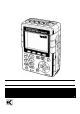
INSTRUCTION MANUAL POWER QUALITY ANALYZER KEW 6310 KYORITSU ELECTRICAL INSTRUMENTS WORKS, LTD.
Contents KEW6310 Contents ········································································································································1 Unpacking ·······································································································································5 Safety warnings ······························································································································7 Section 1 Instrument Overview ·························
KEW6310 Contents Section 6 Instantaneous value measurement············································································· 6.1 6.1 Indications on LCD·································································································· 6.1 6.1.1 Display screen ..........................................................................................................................6.1 6.1.2 Switching displays .........................................................................
Contents KEW6310 9.3 Data saving·············································································································· 9.7 9.3.1 Saving Procedure·····················································································································9.7 9.3.2 Limitations of saving·················································································································9.9 9.3.
KEW6310 11.6 Contents Flicker ······················································································································11.33 Display screen····················································································································· 11.33 Measuring Procedure········································································································· 11.
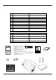
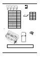
Unpacking Procedure KEW6310 ● Unpacking Procedure We thank you for purchasing the Power Quality Analyzer “KEW6310”. Please check the contents and instrument before use.
KEW6310 13. Clamp sensor (depending on model purchased) Unpacking Procedure 14. Instruction manual for clamp sensor 15.
Safety warnings KEW6310 ● Safety warnings This instrument has been designed, manufactured and tested according to IEC 61010: Safety requirements for Electronic Measuring apparatus, and delivered in the best condition after passing quality control tests. This instruction manual contains warnings and safety rules which have to be observed by the user to ensure safe operation of the instrument and to maintain it in safe condition.
KEW6310 Safety warnings DANGER ● Verify proper operation on a known source before use. ● Verify proper operation on a known source before use or taking action as a result of the indication of the instrument. ● Never make measurement on a circuit in which the electrical potential exceeds AC600V. ● Do not attempt to make measurement in the presence of flammable gasses. Otherwise, the use of the instrument may cause sparking, which can lead to an explosion.
Safety warnings KEW6310 WARNING - Connection ● Confirm that the instrument is off, and then connect the Power cord. ● Connect the Voltage test leads and clamp sensors to the instrument first. Cord to be firmly inserted. ● Never attempt to make any measurement if any abnormal conditions, such as a broken cover or exposed metal parts are present on the Instrument, Voltage test leads, Power cord and Clamp sensor.
KEW6310 Safety warnings CAUTION ● Caution should be taken since conductors under test may be hot. ● Never apply currents or voltages exceeding the maximum allowable input for the instrument for a long time. ● Don’t apply currents or voltages to Voltage test leads or Clamp sensors while the instrument is in off status. ● Don’t use the instrument at dusty places or to be spattered. ● Don’t use the instrument under a strong electric storm or in the vicinity of energized object.
1.1 Functional Overview KEW6310 1. Instrument Overview 1. 1 Functional Overview Instantaneous value measurement Measures average/max/min values of instantaneous values of current, voltage and electric power. See Section 6 “Instantaneous value measurement” for further details. Integration value measurement Measures active/ apparent/ reactive powers on each CH. See Section 7 “Integration value measurement” for further details. Demand measurement Measures demand values based on the preset target values.
KEW6310 1.1 Functional Overview Measurement at WAVE Range Displays vector / waveform of voltages and currents per CH See “WAVE Range (Section 9)” for further details. Harmonic measurement Measures / analyzes harmonic components of current & voltages See “Harmonic Analysis (Section 10)” for further details. Power quality analysis Measures swell, dip, int, transient, inrush current, unbalance ratio and flicker, and also simulates power factor correction with capacitor banks.
1.2 Features KEW6310 1.2 Features This is a Power Quality Analyzer that can be used for various wiring systems. It can be used for simple measurements of instantaneous/ integration/ demand values, and also for monitoring waveforms and vectors, analyzing harmonics and measuring the fluctuations in supply voltages and can perform Capacitance Calculation. Data can be saved either in the internal memory or a CF card, and can be transferred to a PC either via a USB lead or a CF Card reader.
KEW6310 1.2 Features Saving data KEW6310 is endowed with a logging function with a preset recording interval. Data can be saved by manual operation or at pre-set time & date. Screen data can be saved by using Print Screen function. Dual power supply system KEW6310 operates either with AC power supply or with batteries. Both dry-cell batteries (alkaline) and rechargeable batteries (Ni-MH) can be used.
1.3 Connection Diagram KEW6310 1.3 Connection Diagram Current Input Power Cord Voltage Input PC USB Digital Output (1ch) Alkaline dry-cell / Ni-MH Analogue Input (2ch) Recorder / Alarm device Thermometer/Light sensor rechargeable batteries CF Card 1.
KEW6310 1.4 Measuring Procedure 1.4 Measuring Procedure ● Steps for measurement Ensuring your safety See “Safety Warnings”. Preparation See “Section 3: Getting started”. Basic / Measurement / Save Settings See “Section 4: Setting”. Wiring See “Section 5: Wiring”.
1.5 Outline of max demand measurement concept KEW6310 1.5 Outline of max demand measurement concept In some countries, large consumers of electricity will usually have a maximum demand contract with the power company. Such contract varies from country to country. The following is an explanation of a typical Japanese maximum demand contract. ● Maximum Demand contract In such a contract the electricity tariff rates (i.e. for kWhr units) are based upon the consumer’s maximum power demand.
KEW6310 KEW6310 1.5 Outline of max demand measurement concept 1.
2.1 Front View KEW6310 2. Instrument Layout 2.1 Front View Display (LCD) / Keys Display (LCD) Keys LED status indicator Green lights up : Recording & measuring Green flashes : Stand-by (lights up when preset time comes) Red flashes : Charging batteries 2.
KEW6310 2.1 Front View Key Operations Keys Details Power Key Power on / off the instrument LCD ON/OFF Key Display / hide the indications on the LCD Cursor Key Select the setting items, switches screens ENTER Key Confirm entries ESC Key/ RESET Key PRINT SCREEN Key DATA HOLD Key/ KEY LOCK Key Cancel setting changes, clear integration / demand data selected by Cursor Keys. Save the displayed screen as a BMP (bitmap) file. ● Hold the readings.
2.2 Connector KEW6310 2.2Connector Descriptions Voltage Input Terminal (VN, V1, V2, V3) Current Input Terminal (A1, A2, A3, A4) Terminal Cover Power Connector Wiring configuration 2.
KEW6310 2.3 Side Face 2.3 Side Face Descriptions CF Card Cover USB Port Analogue Input/ Digital output USB Connector Eject Button CF Card Slot KEW6310 Analogue Input/ Digital output Terminal 2.
2.4 Battery Case KEW6310 2.4 Battery Case Descriptions Selector Switch Cover Battery Cover Selector switch cover Selector switch * Set the Selector Switch to either “DRY BATTERY” (alkaline) or “RECHARGEABLE BATTERY” (Ni-MH) position depending on the battery you use. 2.
KEW6310 2.5 Marks displayed on the LCD 2.
2.
KEW6310 KEW6310 2.5 Marks displayed on the LCD 2.
3.1.1 Putting a Connector plate on the Input terminal KEW6310 3. Getting started 3.1 Preparation 3.1.1 Putting Input terminal plate on the Input terminal Six Input terminal plates are supplied with this instrument. Choose one Plate which matches the standard cord colors where the instrument is used. Put the Plate to the Input terminal observing the orientation. * Clean the Input terminal before putting the Plate and confirm it isn’t wet.
KEW6310 3.1.2 Attaching Markers to Voltage test leads and Clamp sensors 3.1.2 Attaching Markers to Voltage test leads and Clamp sensors Attach Markers to the both ends of the Voltage test leads and Clamp sensors harmonized with the Input terminals. * Supplied Markers are 32 pcs in total : 4pcs each color (red, blue, yellow, green, brown, gray, black, white). Attach Markers to the both ends of a Sensor. Marker (32 pcs in total) Attach Markers to the both ends of the Voltage test lead. KEW6310 3.
3.2.1 Battery KEW6310 3.2 Power Supply 3.2.1 Battery KEW6310 operates with either an AC power supply or batteries. Capable of performing measurements in the event of AC power interruption, power to the instrument is automatically restored by the batteries installed in the instrument. Dry-cell batteries (alkaline) and rechargeable batteries (Ni-MH) can be both used. It is also possible to charge rechargeable batteries in the instrument. * Dry-cell batteries (alkaline) are supplied as accessories.
KEW6310 3.2.1 Battery Display Mark of power supply changes as follows. AC power supply-operated Battery-operated* mark flashes while charging batteries. Battery Condition Battery mark varies as follows depending on battery condition. Alkaline dry battery (LR6) Ni-MH Rechargeable battery (HR-15/51) * about 2 hours autonomy about 5 hours* autonomy Batteries are exhausted. (Accuracy of readings cannot be guaranteed) In this case, the instrument operates as follows automatically.
3.2.1 Battery KEW6310 Inserting dry-cell batteries 1 Loosen two Battery Cover-fixing screws and remove the Cover. 2 Take out all the batteries. 3 Loosen the screws and remove the Selector Switch Cover. 4 Slide to left and set the Selector Switch to “DRY” position. 5 Install the Selector Switch Cover with the marking of dry battery faced up, and tighten the screws. 6 Insert batteries (LR6 : size AA alkaline batteries) in correct polarity. 7 Install the Battery Cover and tighten two screws.
KEW6310 3.2.1 Battery Rechargeable batteries This instrument can charge rechargeable batteries via AC power supply. 1 Loosen two Battery Cover-fixing screws and remove the Cover. 2 Take out all the batteries. 3 Loosen the screws and remove the Selector Switch Cover. 4 Slide to left and set the Selector Switch to “RE-CHARGEABLE” position. 5 Install the Selector Switch Cover with the marking of rechargeable battery faced up, and tighten the Attention should be paid so as not to lose the screws.
3.2.1 Battery KEW6310 Battery charge starts and the screen returns to normal. ● Charging batteries Indications on the instrument during a charging are as follows. Indications LCD ON Battery mark on the LCD flashes. LED status indicator doesn’t light up. LCD OFF or LED status indicator flashes in red. Instrument is OFF LED status indicator flashes in green while recording data. Slide and set the Selector Switch to the proper position prior to installing the Selector Switch Cover.
KEW6310 3.2.1 Battery Charging cycle is 5 min, and charging patterns vary as follows depending on the instrument condition. This is to control temperature rises on the instrument resulting from battery charge. Pattern I. Power ON (LCD_ON) II. Power ON (LCD_OFF) III. Power OFF KEW6310 Charging Pause 0.7 min 2.1 min 4.2 min 4.3 min 2.9 min 0.8 min Total charging time 48h 14h 7h 3.
3.2.2 AC Power Supply KEW6310 3.2.2 AC Power Supply Check the followings before connecting the Power cord. DANGER ● Use only the Power cord supplied with this instrument. ● Connect the Power cord mains plug to a mains socket outlet. The mains supply voltage must not exceed AC240V. (max rated voltage of supplied Power cord MODEL7169 : AC125V) WARNING ● Confirm that the instrument is powered off, and then connect the Power cord. ● Connect the Power cord to the instrument first. Cord to be firmly inserted.
KEW6310 3.3 Voltage test leads and Clamp sensor connection 3.3 Voltage test leads and Clamp sensor connection Check the followings before connection. DANGER ● Use only the Voltage test leads supplied with this instrument. ● Use the dedicated Clamp sensor for this instrument, and confirm that the measured current rating of the Clamp sensor is not exceeded. ● Do not connect all the Voltage test leads or Clamp sensors unless required for measuring the parameters desired.
3.4.1 Start-up Screen KEW6310 3.4 Start KEW6310 3.4.1 Start-up Screen Hold down the POWER Key until the Start-up screen is displayed. Pressing the POWER Key for 2 sec or more powers off the instrument. Following screen is displayed when the instrument is on. 1 MODEL/VERSION screen is displayed, and a self-check routine starts. Then KEW logo will appear. 2 Previous screens displayed at last operation are back on. 3.
KEW6310 KEW6310 3.4.1 Start-up Screen 3.
3.4.2 Error message KEW6310 3.4.2 Error message Following screen may appear after a self-check routine. ● When a failure is detected; This instrument automatically checks the internal circuit immediately after it is powered on. If a suspect failure in the internal circuit is detected, the error screen below will be displayed for about 5 sec. In this case, refrain from using the instrument and refer to “Section15: Troubleshooting” in this manual.
KEW6310 3.4.2 Error message ● When CF card needs to be formatted; Following screen is displayed for 5 sec when a CF Card has to be formatted. * Only the CF Card formatted via FAT system can be used with this instrument. Select “Yes” to format the CF Card. * All the data saved in the CF Card will be cleared. CF Card cannot be selected as a destination to save data if “No” is selected. Refer to “12.3 CF Card / Internal memory” in this manual which shows how to format a CF Card. KEW6310 3.
4.1 List of Setting items KEW6310 4. Setting 4.1 List of Setting items Settings for measurement condition and data saving are necessary prior to making measurements. Press the Key to enter into SET UP mode and do necessary settings. Setting screens consists of following screens.
KEW6310 4.
4.2.1 Basic Setting KEW6310 4.2 Settings 4.2.
KEW6310 4.2.1 Basic Setting Check of Connection diagram Connection diagram can be viewed at selecting a wiring configuration. Move to a screen for selecting a wiring configuration. Use the configuration, and then press the F4 Key. Cursor Keys to select a wiring Press the F4 Key to display the connection diagram for the selected wiring configuration. Selected connection diagram is displayed.
4.2.1 Basic Setting KEW6310 Setting for Voltage Range 150V 300V 600V 1000V * Default value (or after system reset) : 300V 1 Press the Cursor Keys and select [V Range], and then press the ENTER Key. 2 Press the Cursor Keys and select a desirable voltage value, and then press the ENTER Key. Drop down list appears. Selected voltage value is displayed. 4.
KEW6310 4.2.1 Basic Setting Setting for VT Ratio 0.01 ~ 9999.99 (can be set by 0.01) * Default value (or after system reset) : 1.00 For the details of VT ratio, refer to “5.4 VT / CT Ratio” in this manual. 1 Press the 2 Press the Cursor Keys and select [VT Ratio], and then press the ENTER Key. Cursor Keys and alter the values, and press the ENTER Key to fix it. Box with ▲▼ mark appears at the hundredths' place. Press the Cursor to toggle the value from 0 to 9.
4.2.1 Basic Setting KEW6310 When decreasing a value to 0 in descending sequence, value at the tents' place decreases by 1. Press the Press the Cursor to move to upper places. Cursor to move to lower places. In case that a preset value is 0000.01, the hundreds’ place cannot be altered in descending sequence. Similarly, if a preset value is 9999.99, thousand’s place cannot be altered in ascending sequence. Selected VT ratio is displayed. 4.
KEW6310 4.2.1 Basic Setting Setting for Clamp sensor Model names and rated currents of Clamp sensors are listed as follows.
4.2.1 Basic Setting KEW6310 Manual setting and auto setting both are available for Clamp sensors. << Manual Setting >> 1 Press the 2 Press the Cursor Keys and select [Clamp], and then press the ENTER Key. Cursor Keys and select a Clamp sensor to be used, and then press the ENTER Key. Drop down list appears. Selectable Clamp sensors depend on the selected wiring configurations. Selected Clamp sensor is displayed with corresponding Ch. 4.
KEW6310 4.2.1 Basic Setting When setting for [Clamp] is done, the upper limit of measuring range of the selected sensor is displayed automatically. 3 Press the Cursor Keys and select Clamp sensors to be used at the other CH, and make settings in the same way. Settings for [Clamp] and [A Range] are active in subsequent measurements, but they will change when preset wiring configurations are changed.
4.2.1 Basic Setting KEW6310 << Auto Setting >> Model name of the Clamp sensor connected to the Current Terminal of the instrument is detected automatically at Auto setting mode. Setting for [Wiring] should be done to advance Auto setting. 1 Confirm that settings for [Wiring] are made, and then press the F2 Key. Pressing the F2 Key initiates auto setting for Clamp sensor. Connected Clamp sensors are automatically detected, and settings for [A Range], [CT ratio] and [Filter] are made automatically.
KEW6310 4.2.1 Basic Setting The instrument detects and checks the connected Clamp sensors and the selected wiring configuration, and displays following messages when improper Clamp sensors are connected. < Improper Clamp sensor is detected > Model names of the connected Clamp sensors are displayed. Bars are displayed at A range, CT ratio and Filter boxes. Question mark “?” is displayed at Model name and Current range boxes. CT ratio is automatically set to 1.00. Bars are displayed at Filter box.
4.2.1 Basic Setting KEW6310 Setting for Current Range Available Current Range varies depending on the Clamp sensor to be used. 8128 1/5/10/20/50A/AUTO 8127 10/20/50/100A/AUTO 8126 20/50/100/200A/AUTO 8125 50/100/200/500A/AUTO 8124 100/200/500/1000A/AUTO 8129 300/1000/3000A 8141 8142 100mA/500mA/1A/AUTO 8143 8146 8147 500mA/1/5/10A/AUTO 8148 * Default value (or after system reset) : 200A(8125) 1 4.13 Press the Cursor Keys and select [A Range], and then press the ENTER Key.
KEW6310 2 4.2.1 Basic Setting Press the Cursor Keys and select a Current Range to be used, and then press the ENTER Key. Drop down list appears. Selected Current Range per Ch is displayed. When setting for [Clamp] is done, the upper limit of measuring range of the selected sensor is displayed automatically. 3 Press the Cursor Keys and select Clamp sensors to be used at the other Ch, and make settings in the same way.
4.2.1 Basic Setting KEW6310 Display range and guaranteed accuracy range for each Current Range are as follows. 0.5 50ARange 5 0.2 20ARange 2 0.1 8128 10ARange 0.05 5ARange 0.5 0.01 1ARange 1.2 1.1 0.1 10 0.5 50ARange 5 0.2 20ARange 0.1 10ARange 1 200ARange 8126 11 20 1 100ARange 10 0.5 50ARange 5 0.2 60 55 24 22 2 500ARange 50 2 200ARange 100ARange 20 1 10 0.5 60 55 5 10 1000ARange ゙ 500ARange 50 2 10 3000ARange 47/48 30 0.01 1ARange 0.1 0.005 0.05 0.
KEW6310 4.2.1 Basic Setting Setting for CT ratio 0.01 ~ 9999.99 (can be set by 0.01) * Default value (or after system reset) : 1.00 For the details of CT ratio, refer to “5.4 VT / CT Ratio” in this manual. 1 Press the 2 Setting procedure is same to that for VT ratio. Refer to the procedure described in the Cursor Keys and select [CT Ratio], and then press the ENTER Key. preceding pages. 3 Press the Cursor Keys and select CT ratio for the other Chs, and make settings in the same way. KEW6310 4.
4.2.1 Basic Setting KEW6310 Setting for Filter Lowpass filter activate to cut frequencies in higher harmonic band when set the Filter function “ON”.
KEW6310 4.2.1 Basic Setting Setting for DC V Setting for Voltage Range at analogue input terminal can be made according to the procedure below. 50mV 500mV 5V * Default value (or after system reset) : 5V 1 Press the Cursor Keys and select [DC V], and then press the ENTER Key. 2 Press the Cursor Keys and select a DC Range to be used, and then press the ENTER Key. Drop down list appears. DC Range selected for 1ch is displayed.
4.2.1 Basic Setting KEW6310 Setting for Frequency Frequency of the fixed clock can be changed according to following procedure when PLL synchronized measurement cannot be made. 50Hz 60Hz * Default value (or after system reset) : 50Hz 1 Press the 2 Press the Cursor Keys and select [Freq], and then press the ENTER Key. Cursor Keys and select “50Hz” or “60Hz”, and then press the ENTER Key. Drop down list appears. Selected frequency is displayed. 4.
KEW6310 KEW6310 4.2.1 Basic Setting 4.
4.2.2 Measurement setting (W/Wh/DEMAND) KEW6310 4.2.2 Measurement setting W/ Wh/ DEMAND Press the F1 Key at Measurement setting screen to move to the setting screen for W/ Wh/ DEMAND Range. Setting for interval Interval is a space of the time between data savings; data is saved in a CF card or Internal memory.
KEW6310 4.2.2 Measurement setting (W/Wh/DEMAND) Setting for inst / avg / max / min values Select “ON” for the parameters to be saved. ON⇔OFF * Default value (or after system reset) : ON 1 Press the Cursor Keys and select any of [Inst / Avg / Max / Min], and then press the ENTER Key. Point a parameter to change the setting. 2 Press the Cursor Keys and select “ON” or “OFF”, and then press the ENTER Key. Drop down list appears. ON / OFF is displayed.
4.2.2 Measurement setting (W/Wh/DEMAND) KEW6310 Setting for detailed items Parameters saved under ON or OFF setting for Detailed item are listed below. ON OFF WP+ / WP- O O WS+ / WS- O X WQi+ / WQc+ O O WQi- / WQc- O X Each CH O X ON⇔OFF * Default value (or after system reset) : ON 1 Press the Cursor Keys and select [Detailed item], and then press the ENTER Key. 2 Press the Cursor Keys and select “ON” or “OFF”, and then press the ENTER Key. Drop down list appears.
KEW6310 4.2.2 Measurement setting (W/Wh/DEMAND) Setting for Target demand For the details of target demand, refer to “Section8 Demand measurement” in this manual. 1.000 ~ 999.9(can be set by 0.1) mW/W/kW/MW/GW/TW * Default value (or after system reset) : 300.0kW 1 Press the 2 Press the KEW6310 Cursor Keys and select [Demand Target], and then press the ENTER Key. Cursor Keys and alter the values. 4.
4.2.2 Measurement setting (W/Wh/DEMAND) 3 Use the KEW6310 Cursor Keys and set multipliers. Multiplier Setting As a target demand, values within a range between 1000 and 9999 can be used. To select a value 1000 or less, minus multiplier should be used. 100.0 = 1000 x 10 -1 10.00 = 1000 x 10 -2 1.000 = 1000 x 10 -3 4 Press the Cursor Keys and a select proper unit, and then press the ENTER Key. Selected target demand is displayed. . 4.
KEW6310 4.2.2 Measurement setting (W/Wh/DEMAND) Setting for Demand inspection cycle For the details of Demand inspection cycle, refer to “Section 8 Demand measurement” in this manual.
4.2.2 Measurement setting (W/Wh/DEMAND) KEW6310 1 Press the Cursor Keys and select [Demand Inspection], and then press the ENTER Key. 2 Press the Cursor Keys and select a desirable cycle, and then press the ENTER Key. Drop down list appears. Selected Demand Inspection Cycle is displayed. Demand Inspection Cycle listed on the drop down list depends on the selected interval. Change the interval setting first when a desirable cycle isn’t listed on the drop down list. 4.
KEW6310 KEW6310 4.2.2 Measurement setting (WAVE Range) 4.
4.2.2 Measurement setting (WAVE Range) KEW6310 WAVE Range Setting Press the F2 Key at each Measurement setting screen, and move to the screen for WAVE Range Setting. Setting for interval * Default value (or after system reset) : 30 min * Setting procedure is same to that for interval Setting for W/ Wh/ DEMAND.Refer to the procedure described in the preceding pages. Interval listed on the drop down list depends on the number of save items with “ON” setting.
KEW6310 4.2.2 Measurement Setting (Harmonic Analysis) Harmonic Analysis Press the F3 Key at each Measurement setting screen, and move to the screen for Harmonic Analysis Setting. Setting for interval * Default value (or after system reset) : 30 min * Setting procedure is same to that for interval Setting for W/ Wh/ DEMAND.Refer to the procedure described in the preceding pages. Interval listed on the drop down list depends on the number of save items with “ON” setting.
4.2.2 Measurement Setting (Harmonic Analysis) KEW6310 Setting for allowable range For the details of allowable range of Harmonic Analysis, refer to “Section10 Harmonic analysis” in this manual. Default value (can be set by 0.1) Customize (can be set by 0.1) * Default value (or after system reset) : Default value Either default values listed in the below table or customized values can be used. Default values 1 ---- 2 2.0 3 5.0 4 1.0 5 6.0 6 3.0 7 5.0 8 0.5 9 1.5 10 0.5 11 3.5 12 0.
KEW6310 4.2.2 Measurement Setting (Harmonic Analysis) < Adopting default values > 1 Press the Cursor Keys and select [Allowable range], and then press the ENTER Key. 2 Press the Cursor Keys and select [Default Value], and then press the ENTER Key. Drop down list appears. 3 Selectable default value is displayed. Press the Cursor Keys and point [OK] to accept the value and press the ENTER Key.
KEW6310 4.2.2 Measurement Setting (Harmonic Analysis) < Adopting customized values > 1 Press the Cursor Keys and select [Allowable range], and then press the ENTER Key. 2 Press the Cursor Keys and select [Customize], and then press the ENTER Key. Drop down list appears. 3 Press the Cursor Keys and select the order to be changed, and then press the ENTER Key. 4 According to the procedure to change VT ratio described at preceding page and alter the values.
4.2.2 Measurement Setting (Harmonic Analysis) 5 KEW6310 Press the Cursor Keys and move the cursor to [OK], and press the ENTER Key. To cancel the alternations of values, move the cursor to [Cancel], and press the ENTER Key. Then Screen returns to 1 . Point the cursor here. Indicating that allowable ranges are customized. KEW6310 4.
KEW6310 4.2.2 Measurement Setting (Harmonic Analysis) Setting for MAX HOLD For the details of Max Hold in Harmonic Analysis, refer to “Section10 Harmonic analysis” in this manual. ON⇔OFF * Default value (or after system reset) : ON 1 Press the Cursor Keys and select [MAX Hold], and then press the ENTER Key. 2 Press the Cursor Keys and select “ON” or “OFF”, and then press the ENTER Key. Drop down list appears. ON or OFF is displayed. 4.
4.2.2 Measurement Setting (Harmonic Analysis) KEW6310 Setting for saving items Parameters with “ON” setting will be saved. V ON⇔OFF A * Default value (or after system reset) : ON (all items) 1 Press the Cursor Keys and select a parameter to be changed, and then press the ENTER Key. 2 Press the Cursor Keys and select “ON” or “OFF”, and then press the ENTER Key. Drop down list appears. Setting of the selected item is displayed.
KEW6310 4.2 .2 Measurement Setting (QUALITY-Swell, Dip, Int Measurement) QUALITY Press the F4 Key at Measurement setting screens to move to the QUALITY setting screen. Access to “QUALITY” from Measurement Setting Tab, and press the Cursor Keys and select : Swell / Dip / Int, Transient, Inrush current, Unbalance rate, Capacitance calculation and Flicker measurement*. * Flicker measurement function is only available with ver.2.00 or later.
4.2.2 Measurement Setting (QUALITY-Swell, Dip, INT Measurement) KEW6310 Setting for interval Interval is a space of the time between data savings; data is saved in a CF card or Internal memory. * Default value (or after system reset) : 30 min * Setting procedure is same to that for interval Setting for W/ Wh/ DEMAND.Refer to the procedure described in the preceding pages.
KEW6310 4.2.2 Measurement Setting (QUALITY-Swell, Dip, Int Measurement) Setting for Transient Voltage Range Transient (on 1V basis) 70~150V 151~300V 301~600V 601~1000V 50~310Vpeak 90~630Vpeak 170~1270Vpeak 340~2000Vpeak * Default value (or after system reset) : 210V * Vrms value (Vpeak divided by √2) is automatically calculated when Vpeak is set. 1 Press the 2 Press the Cursor Keys and select [Transient], and then press the ENTER Key.
4.2.2 Measurement Setting (QUALITY-Swell, Dip, INT Measurement) KEW6310 Setting for swell 100 ~ 200% (can be set by 1%) * Default value (or after system reset) : 110% 1 Press the 2 Press the Cursor Keys and select [Swell], and then press the ENTER Key. Cursor Keys and alter values, and then press the ENTER Key. Box with ▲▼ mark appears at the rightmost digit. Selected swell is displayed. KEW6310 4.
KEW6310 4.2.2 Measurement Setting (QUALITY-Swell, Dip, INT Measurement) Setting for dip 5~ 100% (can be set by 1%) * Default value (or after system reset) : 90% 1 Press the 2 Press the Cursor Keys and select [Dip], and then press the ENTER Key. Cursor Keys and alter values, and then press the ENTER Key. Box with ▲▼ mark appears at the rightmost digit. Selected dip is displayed. Lower limit varies depending on the selected reference voltage. ● 70 ~ 150V : percentage to obtain values of 7.
4.2.2 Measurement Setting (QUALITY-Swell, Dip, INT Measurement) KEW6310 Setting for int (short interruption) 5 ~ 98% (can be set by 1%) * Default value (or after system reset) : 10% 1 Press the 2 Press the Cursor Keys and select [Short interruption], and then press the ENTER Key. Cursor Keys and alter values, and then press the ENTER Key. Box with ▲▼ mark appears at the rightmost digit. Selected int value is displayed. Lower limit varies depending on the selected reference voltage.
KEW6310 4.2.2 Measurement Setting (QUALITY-Swell, Dip, INT Measurement) Setting for hysteresis 1 ~ 10% (can be set by 1%) * Default value (or after system reset) : 5% 1 Press the 2 Press the Cursor Keys and select [Hysteresis], and then press the ENTER Key. Cursor Keys and alter values, and then press the ENTER Key. Box with ▲▼ mark appears at the rightmost digit. Selected hysteresis is displayed. 4.
4.2.2 Measurement Setting (QUALITY-Swell, Dip, INT Measurement) KEW6310 Setting for trigger point Trigger to start and stop recording, when a preset threshold is exceeded, is decided based on the number of recorded data. Past: 0 ~ 200 (can be set by 1) Next : 200 ~ 0 (can be set by 1) * Default value (or after system reset) : 100 Example of Trigger Pint Setting: Setting item e.g.
4.2.2 Measurement Setting (QUALITY-Swell, Dip, INT Measurement) 1 Press the 2 Press the KEW6310 Cursor Keys and select [Trigger point], and then press the ENTER Key. Cursor Keys and alter values, and then press the ENTER Key. Box with ▲▼ mark appears at the rightmost digit. Selected trigger point is displayed. When setting a trigger point for “Past”, the point for “Next” is automatically decided. (total 200 data pts) 4.
KEW6310 KEW6310 4.2.2 Measurement Setting (QUALITY-Swell, Dip, INT Measurement) 4.
4.2.2 Measurement Setting (QUALITY-Transient Measurement) KEW6310 Setting for transient measurement For the details of Transient Measurement, refer to “11.3 Transient measurement” in this manual.
KEW6310 4.2.2 Measurement Setting (QUALITY-Transient Measurement) Setting for interval * Default value (or after system reset) : 30 min * Setting procedure is same to that for interval Setting for W/ Wh/ DEMAND.Refer to the procedure described in the preceding pages. Setting for voltage range 150/ 300/ 600/ 1000V * Default value (or after system reset) : 1000V 1 Press the Cursor Keys and select [V Range], and then press the ENTER Key.
4.2.2 Measurement Setting (QUALITY-Transient Measurement) KEW6310 Setting for threshold Voltage Range Threshold (on 1V basis) 150V 300V 600V 1000V 50~310Vpeak 90~630Vpeak 170~1270Vpeak 340~2000Vpeak * Default value (or after system reset) : 1415V * Vrms value (Vpeak divided by √2) is automatically calculated when Vpeak is set. 1 Press the 2 Press the Cursor Keys and select [Threshold Value], and then press the ENTER Key. Cursor Keys and alter the values, and press the ENTER Key to fix it.
KEW6310 4.2.2 Measurement Setting (QUALITY-Transient Measurement) Setting for hysteresis 1 ~ 10% (can be set by 1%) * Default value (or after system reset) : 5% * Setting procedure is same to that for Hysteresis Setting for Swell, Dip, Int measurement. Refer to the procedure described in the preceding pages.
4.2.2 Measurement Setting (QUALITY-Inrush Current Measurement) KEW6310 Setting for Inrush Current Measurement For the details of Inrush Current, refer to “11.4 Inrush Current Measurement” in this manual.
KEW6310 4.2.2 Measurement Setting (QUALITY-Inrush Current Measurement) 1 Press the 2 Press the Cursor Keys and select [A_Referene], and then press the ENTER Key. Cursor Keys and alter the values, and press the ENTER Key to fix it. Box with ▲▼ mark appears at the rightmost digit. Selected reference current is displayed.
4.2.2 Measurement Setting (QUALITY-Voltage Unbalance Ratio KEW6310 Setting for unbalance rate measurement For the details of Voltage Unbalance Rate Measurement, refer to “11.5 Unbalance Rate” in this manual. Setting Items Interval : set interval time Output threshold : set threshold for the output of voltage unbalance rate Setting for interval * Default value (or after system reset) : 30 min * Setting procedure is same to that for interval Setting for W/ Wh/ DEMAND.
KEW6310 4.2.2 Measurement Setting (QUALITY-Flicker) Setting for Flicker measurement For the details of Flicker measurement, refer to “11.6 Flicker measurement” in this manual.
4.2.2 Measurement Setting (QUALITY-Flicker) 2 Select a desirable filter factor with KEW6310 Cusor Key and press the ENTER Key. Drop down list appears. Selected filter factor will be displayed. Setting for Output item Follow the procedure below to make setting for output items. (conditions for output to Output terminal) Pst(1min)/Pst/Plt * Default value (or after system reset) : Pst(1miin) * where : Output item = Pst, Output threshold = 1.
KEW6310 4.2.2 Measurement Setting (QUALITY-Flicker) Setting for output threshold 0.8~20.0(can be set by 0.1) * Default value (or after system reset) :1.0 * Setting procedure is same to that for Output Threshold described in the clause of “Setting for Unbalance rate“. Refer to the procedure described in the preceding pages. KEW6310 4.
4.2.2 Measurement Setting (QUALITY-Capacitance calculation KEW6310 Setting for capacitance calculation For the details of unbalance rate Measurement, refer to “11.7 Capacitance Calculation” in this manual. Setting items Interval : select interval Target power factor : simulating power factor correction with capacitor banks Setting for interval * Default value (or after system reset) : 30 min * Setting procedure is same to that for interval Setting for W/ Wh/ DEMAND.
KEW6310 KEW6310 4.2.2 Measurement Setting (QUALITY-Capacitance calculation 4.
4.2.3 Save Setting KEW6310 4.2.3 Save Setting Setting for recording Manual⇔ Timer * Default value (or after system reset) : Timer 1 Press the Cursor Keys and select [REC method], and then press the ENTER Key. 2 Press the Cursor Keys and select Manual or Timer, and then press the ENTER Key. Drop down list appears. Selected recording method is displayed. Recording start / stop time isn't selectable if Manual recording has been selected. 4.
KEW6310 4.2.3 Save Setting Setting for recording start Recording starts when a preset date and time comes. Recording method MANUAL Display -----/--/-- --:--:-- Year//Month/Date Hour:Minute:Second Invalid Minute indication is rounded to the nearest 30 min ahead. When present time is 28 ~ 30 min or 58 ~ 00 min, time indication is rounded to the nearest 1 hour ahead.
4.2.3 Save Setting KEW6310 Setting for recording end Recording stops when preset date and time comes. Recording method MANUAL Display -----/--/-- --:--:-- Display at setting (at step 1 below) Invalid AUTO Year//Month/Date Hour:Minute:Second Start time + 1 hour When a preset start time is behind the present time, time indication is rounded to the nearest 30 min ahead plus 1 hour.
KEW6310 4.2.3 Save Setting Destination for saving data Internal Memory / CF Card * Data is saved to a CF card automatically under default setting or after system reset when a CF card has been inserted before powering on the instrument. * For the details of destination for saving data, refer to “12.1 CF Card / Internal Memory” in this manual. 1 2 Press the Cursor Keys and select [Save data to:], and then press the ENTER Key.
4.2.3 Save Setting KEW6310 Destination for saving screenshot Internal Memory / CF Card * Data is saved to a CF card automatically under default setting or after system reset when a CF card has been inserted before powering on the instrument. * For the details of destination to save data, refer to “12.1 CF Card / Internal Memory” in this manual. 4.63 1 Press the 2 Setting procedure is same to that for destination for saving data. Refer to “Destination for saving data” described at the preceding pages.
KEW6310 4.2.3 Save Setting Formatting CF Card All the saved data in the CF Card is cleared after formatting the CF Card. Backing up the necessary data prior to a format is recommended. 1 Press the 2 Press the Cursor Keys and select [CF Card Formatting], and then press the ENTER Key. Cursor Keys and select “Yes” or “No”, and then press the ENTER Key. Dialogue appears. if a CF Card isn’t inserted; above dialogue doesn’t appear and a message “No CF Card” is displayed.
4.2.3 Save Setting KEW6310 Deleting the data in CF Card 1 Press the ENTER Key. Cursor Keys and select [CF Card data deletion], and then press the 2 Press the ENTER Key. Cursor Keys and select a file to be deleted and check the box with the Check the box. File size display: Press the Cursor Keys to see file size and updated date& time. if a CF Card isn’t inserted; above dialogue doesn’t appear and a message “No CF Card” is displayed.
KEW6310 4.2.3 Save Setting Press the F1 Key to select all files. Press the F1 Key again to cancel the selection. 3 Press the F2 Key to confirm the selection. Check boxes, and then “OK” Button appears. 4 Press the Cursor Keys and select “Yes” or “No”, and then press the ENTER Key. Number of selected file is displayed. Dialogue appears. 5 Selecting “Yes” initiates deleting the data in CF Card. Deletion completes when a message “Finished!” is displayed on the LCD.
4.2.3 Save Setting KEW6310 Formatting internal memory * All data in the Internal memory will be deleted after formatting. Backing up necessary data prior to a format is recommended. 1 Press the ENTER Key. 2 Press the Cursor Keys and select [Internal Memory Formatting], and then press the Cursor Keys and select “Yes” or “No”, and then press the ENTER Key. Dialogue appears. 3 Selecting “Yes” initiates formatting the Internal Memory.
KEW6310 4.2.3 Save Setting Deleting the data in Internal Memory 1 Press the ENTER Key. Cursor Keys and select [Internal Memory data deletion], and then press the 2 Press the ENTER Key. Cursor Keys and select a file to be deleted, and check the box with the Check the box. File size display: Press the Cursor Keys to see file size and updated date& time. if no deletable file exists; dialogue doesn’t appear and a message “No deletable file” is displayed. Press the F1 Key to select all the files.
4.2.3 Save Setting 3 KEW6310 Press the F2 Key to confirm the selection. Check boxes, and then “OK” Button appears. 4 Press the Cursor Keys and select “Yes” or “No”, and then press the ENTER Key. Number of selected file is displayed. Dialogue appears. 5 Selecting “Yes” initiates deleting the data in Internal Memory. Deletion completes when a message “Finished!” is displayed on the LCD. Formatting doesn’t start when “No” is selected, and returns to File selection screen.
KEW6310 4.2.3 Save Setting Data Transfer * Data saved in the internal memory remains after data transfer. 1 Press the ENTER Key Cursor Keys and select [Data transfer (MEM → CF)], and then press the if a CF Card isn’t inserted; no dialogue appears and a message “No CF Card” is displayed. if a CF Card hasn’t been formatted; no dialogue appears and a message “Unformatted CF Card” is displayed. if no procesable file exists; dialogue doesn’t appear and a message “No processable file” is displayed.
4.2.3 Save Setting 3 KEW6310 Press the F2 Key to determine the selection. Check boxes, and then “OK” Button appears. 4 Press the Cursor Keys and select “Yes” or “No”, and then press the ENTER Key. Number of selected file is displayed. 5 Selecting “Yes” initiates data transfer. Data transfer completes when a message “Finished!” is displayed on the LCD.. Formatting doesn’t start when “No” is selected, and return to File selection screen. * Press the ESC Key to return to the Save setting screen.
KEW6310 4.2.3 Save Setting If the same file name exists, following dialogue appears. Press the Cursor Keys and select “Yes” or “No”, and then press the ENTER Key. Selecting “Yes” initiates data transfer and old files are overwritten. Selecting “No” cancels data transfer. * Backing up the necessary data prior to data transfer to prevent old data from being overwritten. If data transfer fails, following dialogue appears. Check free area and number of files in a CF card, and try again. KEW6310 4.
4.2.3 Save Setting KEW6310 Load setting Preset settings saved at [Save Setting] is loaded. 1 Press the Cursor Keys and select [Load Setting], and then press the ENTER Key. 2 Press the Cursor Keys and select a file to be loaded, and then press the ENTER Key. Select a file to be Loaded. Press the F1 Key to switch the list of the files in Internal memory and CF Card. 3 Load of setting starts. A message “Setting for following file completes.” is displayed.
KEW6310 4.2.3 Save Setting Setting save This instrument can memorize and recall user’s preferred settings once it has been saved. 1 Press the 2 Press the Cursor Keys and select [Save Setting], and then press the ENTER Key. Cursor Keys and select CF (CF Card) or MEM (Internal memory) to save settings, and then press the ENTER Key. 3 Setting is saved. A message “Following file is saved.” is displayed. KEW6310 4.
4.2.4 Other Setting KEW6310 4.2.4 Other Setting Language Selection Japanese ⇔ English * System reset doesn’t affect language setting. 1 Press the Cursor Keys and select [Language], and then press the ENTER Key. 2 Press the Key. Cursor Keys and select “Japanese” or “English”, and then press the ENTER Drop down list appears. Selected language is displayed. 4.
KEW6310 4.2.4 Other Setting Setting for date format e.g. June 15th, 2006 YYYY / MM / DD 2006 / 06 / 15 MM / DD / YYYY 06 / 15 / 2006 DD / MM / YYYY 15 / 06 / 2006 * Default value (or after system reset) : MM / DD / YYYY 1 Press the Cursor Keys and select [Date], and then press the ENTER Key. 2 Press the Key. Cursor Keys and select a desirable date format, and then press the ENTER Drop down list appears. Selected date format is displayed. KEW6310 4.
4.2.4 Other Setting KEW6310 Setting for current date & time 2000 / 01 / 01 00:00:00 ~ 2099 / 12 / 31 23:59:59 * System reset doesn’t affect the preset current date and time. 1 Press the 2 Select and modify the date/time parameters desired with press the ENTER Key. Cursor Keys and select [Time], and then press the ENTER Key. Cursor Keys, and then Box with ▲▼ mark appears at second place. Set date and time is displayed. 4.
KEW6310 4.2.4 Other Setting Setting for buzzer ON⇔OFF * Default value (or after system reset) : ON 1 Press the Cursor Keys and select [Buzzer], and then press the ENTER Key. 2 Press the Cursor Keys and select “ON” or “OFF”, and then press the ENTER Key. Drop down list appears. Selected setting is displayed. KEW6310 4.
4.2.4 Other Setting KEW6310 Setting for CSV file Select the decimal points and separators to be used in the saved data. Setting needs to be changed depending on the language setting. Default setting is applicable to normal use. Decimal Point / Separator ./, ./; ,/; * Default value (after system reset) : Decimal point/ Separator = . / , 1 Press the Cursor Keys and select [CSV File], and then press the ENTER Key. 2 Press the Cursor Keys and select a desirable one, and then press the ENTER Key.
KEW6310 4.2.4 Other Setting Setting for ID number The number selected at the step is saved in save files. It is useful to identify data when using multiple instruments and recorded data at various places. 00-001 ~ 99-999 * Default value (or after system reset) : 00-001 1 Press the 2 Press the ENTER Key. Cursor Keys and select [ID No.], and then press the ENTER Key. Cursor Keys and select a desirable number, and then press the Drop down list appears. Selected ID No. is displayed. KEW6310 4.
4.2.4 Other Setting KEW6310 Setting for LCD contrast Light ⇔ Standard ⇔ Dark 10 ⇔ 0 ⇔ 10 * Default value (or after system reset) : Standard 1 2 Press the Press the Key. Cursor Keys and select [LCD contrast], and then press the ENTER Key. Cursor Keys and select a desirable contrast level, and then press the ENTER Slide bar appears. Selected contrast is displayed. 4.
KEW6310 4.2.4 Other Setting Setting for CH color Default setting Customization * System reset doesn’t affect the setting for CH Color.. 1 Press the 2 Press the Cursor Keys and select “Customize”, and then press the ENTER Key. * Default color setting becomes effective when selecting “Default Value”. 3 Press the Cursor Keys and select the color which is subject to change, and then press the ENTER Key. Cursor Keys and select [CH Color], and then press the ENTER Key. Drop down list appears.
4.2.4 Other Setting 4 Press the Key. 5 Press the KEW6310 Cursor Keys and choose desirable colors and then press the ENTER Cursor Keys and point “OK”, and then press the ENTER Key. Pressing the ENTER Key activates color change. Color change doesn’t activate when selecting “Cancel”, and return to Setting screen. System reset doesn’t affect the customized settings. 4.
KEW6310 4.2.4 Other Setting Setting for Auto-power-off ON⇔OFF * Default value (or after system reset) : ON * The instrument is automatically powered off when 5 min passes without any Key operation. (O = Auto-power-off / activate , X = Auto-power-off / disable) AC-power-supply Battery operated operated LCD OFF O O LCD ON X O X X Recording (stand-by) 1 Press the Cursor Keys and select [Auto Power Off], and then press the ENTER Key.
4.2.4 Other Setting KEW6310 Setting for LCD Auto-off Indications on the LCD are hidden with “ON” setting to prevent screen from burning and to save battery during recordings ON⇔OFF * Default value (or after system reset) : ON * Indications on the LCD disappear automatically powered off when 5 min passes without any Key operation. 1 Press the Cursor Keys and select [LCD Auto-off], and then press the ENTER Key. 2 Press the Cursor Keys and select “ON” or “OFF”, and then press the ENTER Key.
KEW6310 4.2.4 Other Setting Battery charge Set the Selector switch to “RE-CHARGEABLE” position prior to starting battery charge. For further details, refer to “3.2 Power supply” in this manual. ON⇔OFF * Default value (or after system reset) : OFF 1 Press the Cursor Keys and select [Battery Charge], and then press the ENTER Key. 2 Press the Cursor Keys and select “ON” or “OFF”, and then press the ENTER Key. Drop down list appears.
4.2.4 Other Setting KEW6310 The window closes and Setting screen appears when “No” is selected. In this case, batteries aren’t charged. when the Selector switch isn’t set to “RE-CHARGEABLE” position, following message appears and battery charge won’t start. 4.
KEW6310 4.2.4 Other Setting System reset Settings restore to default after system reset. 1 Press the Cursor Keys and select [System Reset], and then press the ENTER Key. 2 Press the Cursor Keys and select “Yes” or “No”, and then press the ENTER Key. 3 Select “Yes” to initiates system reset. System reset completes when “Finished!” is displayed on the LCD. Selecting “No” returns to Setting screen. Following parameters don’t restore to default after system reset.
5.1 Important Preliminary Checks KEW6310 5. Wining Configurations 5.1 Important preliminary checks DANGER ● Do not make measurements on a circuit in which electrical potential exceeds AC600V. ● Connect the Power cord to a socket outlet. Never connect it to the socket outlet of AC240V or more. ● The Clamp sensor, Voltage test leads and Power cord are to be connected to the instrument first.
KEW6310 5.2 Basic Wiring Configuration 5.2 Basic Wiring Configuration 1. “1P2W x 1” Wiring method for single-phase 2-wire (1ch) Source L L N N VN V1 V2 V3 A1 A2 A3 Load A4 2. “1P2W x 2” Wiring method for single-phase 2-wire (2ch) Source L L N N Load 1 L N VN V1 V2 V3 A1 A2 A3 Load 2 A4 3. “1P2W x 3” Wiring method for single-phase 2-wire (3ch) Source L L N N Load 1 L N Load 2 L N VN V1 KEW6310 V2 V3 A1 A2 A3 Load 3 A4 5.
5.2 Basic Wiring Configuration KEW6310 4. “1P2W x 4” Wiring method for single-phase 2-wire (4ch) Source L L N N Load 1 L Load 2 N L N Load 3 L N VN V1 V2 V3 A1 A2 A3 Load 4 A4 5. “1P3W x 1” Wiring method for single-phase 3-wire (1ch) L1 L1 Source N N L2 Load 3P3W L2 VN V1 V2 V3 A1 A2 A3 A4 6. “1P3W x 2” Wiring method for single-phase 3-wire (2ch) Source L1 L1 N N L2 L2 Load 1 1P3W L1 N Load 2 1P3W L2 VN V1 5.
KEW6310 5.2 Basic Wiring Configuration 7. “1P3W x1 +2A” Wiring method for single-phase 3-wire (1ch) + 2-current Source L1 L1 N N L2 L2 VN V1 V2 V3 A1 A2 A3 Load 1P3W A4 8. “3P3W x1” Wiring method for three-phase 3-wire (1ch) Source L1(R) L1(R) L2(S) L2(S) L3(T) L3(T) VN V1 V2 V3 A1 A2 A3 Load 3P3W A4 9.
5.2 Basic Wiring Configuration KEW6310 10. “3P3W x1 +2A” Wiring method for three-phase 3-wire (1ch) + 2-current Source L1(R) L1(R) L2(S) L2(S) L3(T) L3(T) VN V1 V2 V3 A1 A2 A3 Load 3P3W A4 11. “3P3W 3A” Wiring method for three-phase 3-wire + 3-current Source L1(R) L1(R) L2(S) L2(S) L3(T) L3(T) VN V1 V2 V3 A1 A2 A3 Load 3P3W A4 12. “3P4W (1ch)” Wiring method for three-phase 4-wire (1ch) Source L1(R) L1(R) L2(S) L2(S) L3(T) L3(T) N N VN V1 5.
KEW6310 5.2 Basic Wiring Configuration 13. “3P4W x1 +1A” Wiring method for three-phase 4-wire (1ch) + 1-current Source L1(R) L1(R) L2(S) L2(S) L3(T) L3(T) N Load 3P4W N VN V1 V2 V3 A1 A2 A3 A4 0 4A 4-current VN V1 KEW6310 V2 V3 A1 A2 A3 A4 5.
5.3.1 Checking procedure KEW6310 5.3 Wiring check Proper wirings can be checked at WAVE Range. 5.3.1 Checking procedure 1 Select the WAVE Range with Key and press the F2 Key. 2 Wiring check routine starts. Status is indicated when checking starts. Correct vector (varies depending on wiring configurations) 3 Wiring check complets. OK is indicated if the connection is appropriate, and NG is displayed if the connection is improper. NG parameters are displayed with flashing. 5.
KEW6310 5.3.2 Criteria of Judgment Check screen In case of NG, Error message appears. (Press the ENTER Key when OK is displayed.) * Check results may be affected if great power factors exist at the measurement sites. 5.3.2 Criteria of Judgment Check Frequency Voltage input Criteria of Judgment Frequency of V1 is between 42 and 68Hz. Voltage input is 10% or more of (Voltage Range x VT).
5.4 VT/ CT KEW6310 5.4 Using supplementary VT/CT’s (not supplied with the instrument) DANGER ● Never make measurement on a circuit in which electrical potential exceeds AC600V. ● Connect the Power cord to a socket outlet. Never connect it to the socket outlet of AC240V or more. ● This instrument must be used on the secondary side of VT(transformer) and CT(current transformer).
KEW6310 KEW6310 5.4 VT/ CT 5.
6.1.1 Instantaneous value measurement-Display screen KEW6310 6. Instantaneous value measurement 6.1 Indications on LCD 6.1.1 Display Screen Press the Key to display a list for W Range. Power Source / Time Measured/ calculated value at each Range System Item Frequency Sum of the measured values at each Range Interval Function Measured analogue inputs Symbol displayed on the LCD V S An 6.
KEW6310 6.1.1 Instantaneous value measurement -Display screen Displayed contents are depending on the selected wiring configurations. Followings are displayed in a list depending on the selected wiring configurations. 1. 1P2W × 1 Single-phase 2-Wire (1CH) V ● A ● P ● Q ● S ● PF ● DC1 ● PA ● DC2 ● f ● 2.
6.1.1 Instantaneous value measurement -Display screen KEW6310 3. 1P2W × 3 Single-phase 2-Wire (3CH) 1 CH 2 CH 3 CH V ● V ● V ● A ● A ● A ● P ● P ● P ● Q ● Q ● Q ● S ● S ● S ● PF ● PF ● PF ● PA ● PA ● PA ● P ● P ● P ● Q ● Q ● Q ● S ● S ● S ● f ● f ● f ● PF ● DC1 ● PF ● DC1 ● PF ● DC1 ● PA ● DC2 ● PA ● DC2 ● PA ● DC2 ● Sum of and and 4.
KEW6310 6.1.1 Instantaneous value measurement -Display screen 5. 1P3W × 1 Single-phase 3-Wire (1CH), 7. 1P3W × 1 + 2A Single-phase 3-Wire (1CH) + 2-current 1ch 2ch V ● ● A ● ● P ● ● Q ● ● S ● ● PF ● ● PA ● ● P ● f Q ● * A3 ● S ● * A4 ● PF ● DC1 ● PA ● DC2 ● Sum of ● * is displayed only when making setting of 7. 1P3W×1 + 2A and 6.
6.1.1 Instantaneous value measurement -Display screen KEW6310 8. 3P3W × 1 Three-phase 3-Wire (1CH), 10. 3P3W × 1 + 2A Three-phase 3-Wire (1CH) + 2-current 1ch 2ch V ● ● ● A ● ● ● P ● ● Q ● ● S ● ● PF ● ● PA ● ● P ● f Q ● * A3 ● S ● * A4 ● PF ● DC1 ● PA ● DC2 ● Sum of Calculated by vector operation ● * is displayed only when making setting of 10. 3P3W×1 + 2A and 9.
KEW6310 6.1.1 Instantaneous value measurement -Display screen 11. 3P3W3A Three-phase 3-Wire 3A 1ch 2ch 3ch V ● ● ● A ● ● ● P ● ● ● Q ● ● ● S ● ● ● PF ● ● ● PA ● ● ● P ● f ● Q ● S ● PF ● DC1 ● PA ● DC2 ● Sum of and and 12. 3P4W × 1 Three-phase 4-Wire (1CH), 13.
6.1.1 Instantaneous value measurement -Display screen 0 KEW6310 4A 1CH A1 ● A2 ● A3 ● A4 ● DC1 ● DC2 ● 6.
KEW6310 6.1.2 Instantaneous value measurement -Switching displays 6.1.2 Switching displays Switching systems Press the Cursor Keys and view displays for each system. Switching items Press the Cursor Keys and view the instantaneous, average values etc. * Displayed contents are depending on the selected wiring configurations. * ∑ means the total of the values at each channel. Viewing the present settings Press the ENTER Key to check the present settings.
6.1.3 Instantaneous value measurement -Zoom KEW6310 6.1.3 Zoom Default setting or the setting after system reset is depending on the selected wiring configurations. Pressing the F3 Key while a list for Instantaneous Value Measurement is being displayed zooms the list. Press the F3 Key again to return to the list display. 6.
KEW6310 6.1.3 Instantaneous value measurement -Zoom Customizing the Zoom screen 1 Press the ENTER Key. Cursor Keys and select the item to be customized, and then press the Measuring items Items Point the item to be customized with cursor. 2 Press the Cursor Keys and select any items, and then press the ENTER Key. Selectable measuring items Drop-down list appears when a parameter is pointed by cursor. Item will be listed when a measured value is pointed by cursor.
6.2 Instantaneous value measurement -Measuring Procedure KEW6310 6.2 Measuring Procedure Steps for measurement Ensuring your safety See “Safety Warnings”. ↓ Getting started See “Section 3 Getting started”. ↓ Setting See “Section 4 Setting”. ↓ Wiring See “Section 5 Wiring Configuration”. ↓ Inst value measurement See this section.
KEW6310 6.3.1 Instantaneous value measurement -Saving procedure 6.3 Data Saving 6.3.1 Saving Inst measurement data Saving procedure 1 Press the F1 Key at the List or Zoom screen. 2 Press the F4 Key and check the Basic, Measurement and Save settings. Press the Cursor Keys to select and modify the settings. Pressing the F3 Key returns to the previous screen.
6.3.1 Instantaneous value measurement -Saving procedure 3 KEW6310 Manually start saving data, or press the F4 Key. Stand-by screen (WAIT) appears if saving start date and time has been specified. Flashes. Flashes. File name for saving data is displayed. 4 Saving starts and the LED status indicator lights up. Flashes Destination for saving data will be highlighted and flashes in red. No setting change can be made during data saving . Press the F4 Key to check the settings.
KEW6310 6.3.2 Instantaneous value measurement -Limitations of saving 6.3.2 Limitations of saving When data cannot be saved during a measurement, Warning message is displayed. Further data cannot be saved when max number of file or a capacity is exceeded. Previously saved files should be deleted or replaced the CF Card with a new one. For further details, see “Section 12 CF Card / Internal Memory” in this manual. KEW6310 6.
6.3.3 Instantaneous value measurement -Saved data KEW6310 6.3.
KEW6310 6.3.
6.3.3 Instantaneous value measurement -Saving data KEW6310 File format and name Measurement data is saved in CSV format, and the file name is assigned automatically. File name : 01 - CF 001 .csv ① 6.
KEW6310 6.4.1 Instantaneous value measurement -Ranges 6.4 Ranges and Over-range indications 6.4.1 Ranges Ranges and decimal points for the measuring items will be automatically adjusted depending on the settings for Voltage, Current Ranges and VT / CT ratio. Voltage Range : V, Max digit : 4-digit (V Range) x (VT ratio) x (120%) Decimal point & Unit 1.8 ~ 9.999 V 9.999 V 10 ~ 99.99 V 99.99 V 100 ~ 999.9 V 999.9 V 1 ~ 9.999kV 9.999kV 10 ~ 99.99kV 99.99kV 100 ~ 9.999kV 999.9kV 1 ~ 9.999 MV 9.
6.4.1 Instantaneous value measurement -Ranges KEW6310 Power Range : P, Q, S, Max digit : 4-digit, Max digit (to display sum): 5-digit Power x VT x 120% x A x CT x 120% Decimal point & Unit 2.1 ~ 9.999 mW 9.999 mW 10 ~ 99.99 mW 99.99 mW 100 ~ 999.9 mW 999.9 mW 1 ~ 9.999 W 9.999 W 10 ~ 99.99 W 99.99 W 100 ~ 999.9 W 999.9 W 1 ~ 9.999kW 9.999kW 10 ~ 99.99kW 99.99kW 100 ~ 999.9kW 999.9kW 1 ~ 9.999 MW 9.999 MW 10 ~ 99.99 MW 99.99 MW 100 ~ 999.9 MW 999.9 MW 1 ~ 9.999 GW 9.
KEW6310 6.4.1 Instantaneous value measurement -Ranges Power factor: PF, Max : 4-digit - 1 . 0 0 0 ~ 1 . 0 0 0 PF Phase Angle : PA, Max : 4-digit - 1 . 0 0 0 ~ 1 . 0 0 0 PA Frequency: f, Max : 4-digit 40 . 0 0 KEW6310 ~ 7 0 . 0 0 Hz 6.
6.4.2 Instantaneous value measurement -Over-range / Bar indication KEW6310 6.4.2 Over-range / Bar indication Check the followings. WARNING ● When the over-range indication appears on the maximum chosen range, this means that the input exceeds the maximum allowable input for the instrument. Never apply such an input to the instrument. ● When a measured value exceeds the maximum allowable input, the use of VT/CT’s is recommended.
KEW6310 6.4.2 Instantaneous value measurement -Over-range / Bar indication Bar Indication The calculations and measurements performed by this instrument are based on the voltage and frequency of V1. If the value of V1 is less than 5% of the chosen range or if the frequency is not within 40 ~ 70Hz, all the parameters (except for voltage and current ) cannot be computed and thus displayed.
7.1.1 Integration measurement – Display screen KEW6310 7. Integration measurement 7.1 Indications on LCD 7.1.1 Display Screen Press the Key to view WH Range screen. Power source / Time Elapsed time of integration System Measured values Channel Interval Function Symbol displayed on the LCD 7.
KEW6310 7.1.2 Integration measurement – Switching displays 7.1.2 Switching displays Switching systems Press the Cursor Keys and view displays for each system. Switching channels Press the Cursor Keys and view displays for each channel. * Displayed contents depends on the selected wiring configurations. * ∑ means the sum of the values at each channel.
7.1.3 Integration measurement – W Range display KEW6310 7.1.3 W Range display It is possible to access the W Range display screen from the Wh Range screen. 1 Press the F2 Key. Wh Range W Range Pressing the F2 Key again returns to Wh Range display screen. 7.
KEW6310 7.2 Integration measurement – Measuring Procedure 7.2 Measuring Procedure Steps for measurement Ensuring your safety See “Safety Warnings”. ↓ Getting started See “Section 3 Getting started”. ↓ Settings See “Section 4 Setting”. ↓ Wiring See “Section 5 Wiring Configuration”. ↓ Integration value measurement See this section * Readings are displayed right after the recording of integration value measurement starts.
7.3.1 Integration measurement – Saving procedure KEW6310 7.3 Data Saving 7.3.1 Saving Integration measurement data Saving procedure Instantaneous and integration data is saved at the same time when saving integration measurement data. 1 Press the F1 Key at the Wh Range screen. 2 Press the F4 Key to check Basic, Measurement and Save Settings. Press the Cursor Keys to select and modify the settings. Pressing the F3 Key returns to the previous screen.
KEW6310 3 7.3.1 Integration measurement – Saving procedure Manually start saving data, or press the F4 Key. Stand-by screen (WAIT) appears if saving start date and time has been specified. Flashes. Flashes. File name for saving data is displayed. 4 Saving starts and the LED status indicator lights up. Flashes. . Destination for saving data will be highlighted and flashes in red. No setting change can be made during data saving . Press the F4 Key to check the settings.
7.3.2 Integration measurement – Limitations of saving KEW6310 7.3.2 Limitations of saving Refer to “6.3.2 Limitations of saving” in this manual. 7.3.
KEW6310 7.3.
7.4.1 Integration measurement - Ranges KEW6310 7.4 Ranges and Over-range indications 7.4.1 Ranges Ranges and decimal points for the measuring items will be automatically adjusted depending on the Range selected. A range shifts up when integration vaues exceed 999999. Power Range : WP, WS, WQ, Max : 6-digit Decimal point & Unit 0.00000 ~ 9. 99999 m 9.99999 m 10.0000 ~ 99.9999 m 99. 9999 m 100.000 ~ 999. 999 m 999. 999 m 1000.00 ~ 9999.99 m 9999.99 m 10.0000 ~ 99.9999 99.9999 100.000 ~ 999.
KEW6310 KEW6310 7.4.1 Integration measurement - Ranges 7.
8.1.1 Demand Measurement – Display Screen KEW6310 8. Demand Measurement 8.1 Indications on LCD 8.1.1 Display Screen Press the Key to view Demand measurement screen. Power source / Time Screen Interval Function 8.
KEW6310 8.1.1 Demand Measurement – Display Screen Measurement screen Remaining time (time left)/ Target value/ Predicted value / Present value Measured max demand with time and date information Displayed parameters Remaining time (time left) Target value Details Demand interval is counted down. Should be set for each measurement. Predicted demand value (average power) when preset demand interval elapses under present load.
8.1.1 Demand Measurement – Display Screen KEW6310 Shifts in specific period Remaining time (Time left) Load factor / Prediction Target demand Prediction Present value Displayed parameters Details Percentage of the present value against the target value. Load Factor (Present value) (Target value) Percentage of the predicted value against the target value.
KEW6310 8.1.1 Demand Measurement – Display Screen Demand change Measured demand with time and date information Cursor Target demand Recording start Bar Graph date and time A long press of Most recent recorded date and time Cursor Keys changes pages. Displayed parameters Details Cursor Use the Measured max demand with time and date information Demand value is displayed with recorded time & date info where a cursor points.
8.1.2 Demand Measurement – W Range / Wh Range display KEW6310 8.1.2 Switching screens Press the Cursor Keys to switch screens. 8.1.3 W Range / Wh Range display It is possible to access the W / Wh Range display screens from the Demand screen. 1 Press the F2 Key. DEMAND Range W Range Wh Range Pressing the F2 Key again returns to Demand screen. 8.
KEW6310 8.2 Demand Measurement – Measuring Procedure 8.2 Measuring Procedure Steps for measurement Ensuring your safety See “Safety Warnings”. ↓ Getting started See “Section 3 Getting started”. ↓ Settings See “Section 4 Setting”. ↓ Wiring See “Section 5 Wiring Configuration”. ↓ Demand measurement See this section. * Readings are displayed right after the recording of demand measurement starts.
8.3 Demand Measurement – Data Saving KEW6310 8.3 Data Saving Operations within demand intervals (W) Target value Prediction Digital output signal warns when the predicted value exceeds the target value. Target Demand (present value) (Elapsed time) Inspection Inspection Inspection cycle cycle cycle Demand interval Save point Max demand and data saving point (W) Target value Max demand (displayed on Measurement screens) Demand value 0 Start of demand 8.
KEW6310 8.3.1 Demand Measurement – Saving procedure 8.3.1 Saving Demand measurement data Saving procedure Inst measurement data is saved as well as demand data when saving demand measurement data. 1 Press the F1 Key at the Measurement screen. 2 Press the F4 Key to check Basic, Measurement and Save Settings. Basic Setting Measurement Setting Save Setting * Pressing down the F1 Key for 2 sec or more while in the status 1 skips step 2 and starts data save.
8.3.1 Demand Measurement – Saving procedure 3 KEW6310 Manually start saving data, or stand-by screen (WAIT) appears if saving start date and time has been specified. Flashes. File name for saving data is displayed. 4 Saving starts and the LED status indicator lights up. Flashes. Destination to save data will be highlighted and flashes in red. No setting change can be made during data saving . Press the F4 Key to check the settings. 5 Press the F1 Key to stop measurement.
KEW6310 8.3.2 Demand Measurement – Limitations of saving 8.3.2 Limitations of saving Refer to “6.3.2 Limitations of saving” in this manual. 8.3.
8.3.
KEW6310 8.4.1 Demand measurement – Ranges 8.4 Ranges and Over-range indications 8.4.1 Ranges Ranges and decimal points for the measuring items will be automatically adjusted depending on the preset target values. Target value : DEM T, Max : 4-digit Predicted value : DEM G, Present value : DEM P, Max demand : DEM max, Max : 6-digit Decimal point & Unit 1.000 ~ 999.9 mW 99999.9 mW 1.000 ~ 999.9 W 99999.9 W 1.000 ~ 999.9kW 99999.9kW 1.000 ~ 999.9 MW 99999.9 MW 1.000 ~ 999.9 GW 99999.9 GW 1.
9.1.1 WAVE Range – Display Screen KEW6310 9. WAVE Range 9.1 Indications on LCD 9.1.1 Display Screen Press the Key to view Vector screen. Switching screens Press the F3 Key to switch Vector and Waveform screens. Vector screen Voltage and current vectors are displayed. Number of Ch for displayed vector depends on the selected wiring configuration.
KEW6310 9.1.1 WAVE Range – Display Screen Waveform screen Voltage and current waveforms can be displayed together or displayed channel by channel. Number of Ch for displayed waveform depends on the selected wiring configuration. Measured value at each Ch Power source/ Time Magnification CH Waveform Function Keys Symbols displayed on the LCD changing a magnification of voltage changing a magnification of current switching to Vector screen switching to Waveform screen KEW6310 9.
9.1.2 WAVE Range – Switching displays KEW6310 9.1.2 Switching displays Switching channels (waveform screen) Press the Cursor Keys to switch channels. Displayed parameters depend on the selected wiring configuration. Right table indicates: Wiring configuration ⑬3P4W x 1A (Three-phase 4-Wire (1ch) + 1-current) Details of channels ⑬3P4W×1+1A V_ALL : V1/ V2/ V3 A_ALL : A1/ A2/ A3 1ch : V1/ A1 2ch : V2/ A2 3ch : V3/ A3 4ch : A4 Channels to display waveform 9.
KEW6310 9.1.
9.1.3 WAVE Range – Zooming/ downsizing KEW6310 9.1.3 Zooming/ downsizing Magnification Voltage( ) Current( ) 3 2 1 0.5 0.2 0.1 * Default value (or after system reset) : 1 Zooming/ downsizing of Voltage display Press the Cursor Key and select the channel to be zoomed in or out, and then press the F1 Key. Select a channel to change magnification. Magnification changes every time pressing the F1 Key.
KEW6310 9.2 WAVE Range – Measuring Procedure 9.2 Measuring Procedure Steps for measurement Ensuring your safety See “Safety Warnings”. ↓ Getting started See “Section 3 Getting started”. ↓ Settings See “Section 4 Setting”. ↓ Wiring See “Section 5 Wiring Configuration”.
9.3.1 WAVE Range – Saving procedure KEW6310 9.3 Data Saving 9.3.1 Saving Procedure 1 Press the F1 Key at the Vector screen. 2 Press the F4 Key to check Basic, Measurement and Save Settings. Press the Cursor Keys to select and modify the settings. Pressing the F3 Key returns to the previous screen. Basic Setting Measurement Setting Save Setting * Pressing down the F1 Key for 2 sec or more while in status 1, you can skip step 2 and start data saving.
KEW6310 3 9.3.1 WAVE Range – Saving Procedure Manually start saving data, or stand-by screen (WAIT) appears if saving start date and time has been specified. Flashes. File name for saving data is displayed. 4 Saving starts and the LED status indicator lights up. Flashes. Destination to save data will be highlighted and flashes in red. No setting change can be made during data saving . Press the F4 Key to check the settings. 5 Press the F1 Key to stop measurement.
9.3.2 WAVE Range – Limitations of saving KEW6310 9.3.2 Limitations of saving Refer to “6.3.2 Limitations of saving” in this manual. 9.3.3 Saving data Settings 9.
KEW6310 9.3.3 WAVE Range – Save data Save data File ID : 6310-04 (waveform data) Saved time & date Elapsed time Channel DATE TIME ELAPSED TIME CH yyyy/mm/d h:mm:ss h:mm:ss Ai / Vi year/month/ date hour:min:sec st hour:min:sec Inst value *Line 1/ Line 2 1 / 128 ~ 129 / 256 (±)x.xxxxE±nn Current / ±n (±) value x 10 Voltage th *1 ~ 128 measured instantaneous values are saved to the 1st line, 129th ~ 256th are to 2nd line.
9.3.
KEW6310 9.4.1 WAVE Range – Ranges 9.4 Ranges and Over-range indications 9.4.1 Ranges Ranges and decimal points for the measuring items will be automatically adjusted depending on the Range selected. For further details, refer to “6.5.1 Ranges” in this manual. 9.4.2 Over-range / Bar indication Refer to “6.4.2 Over-range / Bar indication Limitations” in this manual. KEW6310 9.
10.1.1 Harmonic Analysis – Display Screen KEW6310 10. Harmonic Analysis 10.1 Indications on LCD 10.1.1 Display Screen Press the Key to view bar graph for harmonics.
KEW6310 10.1.1 Harmonic Analysis – Display Screen ①1P2W x 1 ②1P2W x 2 ③1P2W x 3 V1 V1 V1 A1 A1 A1 A2 A2 A3 ⑥1P3W x 2 ④1P2W x 4 ⑤1P3W x 1 ⑦1P3W x 1+2A ⑧3P3W x 1 ⑨3P3W x 2 ⑩3P3W x 1+2A V1 V1 V1 A1 V2 V2 A2 A1 A1 A3 A2 A2 A4 A3 A4 ⑪3P3W3A ⑫3P4W x 1 ⑬3P4W x 1+1A V1 V1 V2 V2 V3 V3 A1 A1 A2 A2 A3 A3 A4 KEW6310 10.
10.1.1 Harmonic Analysis – Display Screen KEW6310 Graph Exceeding axis value MAX hold ON: displayed while it is activated. Exceeding the Allowable range threshold Red bar graph : present value White bar graph : preset allowable range (refer to clause 4.2.2 for further details) Green mark : max recorded value during a measurement, displayed while MAX HOLD function is activated. Refer to clause 4.2.2 for further details about MAX HOLD function.
KEW6310 10.1.2 Harmonic Analysis – Switching displays 10.1.2 Switching displays Switching channels Press the Cursor Keys to switch channels. Press the Cursor to switch values per order. KEW6310 10.
10.1.3 Harmonic Analysis – Logarithm display KEW6310 10.1.3 Logarithm display Logarithm and +/- displays can be switched over according to following procedures. Logarithm display 1 Press the F2 Key. Linear display with ticks of 0% to 100% and Logarithm display with ticks of 0.1% to 10% are switchable on vertical axis. Linear display Logarithm display Press the F2 Key again to return to Linear display. +/- display 1 Press the F3 Key.
KEW6310 10.2 Harmonic Analysis – Measuring Procedure 10.2 Measuring Procedure Steps for measurement Ensuring your safety See “Safety Warnings”. ↓ Getting started See “Section 3 Getting started”. ↓ Settings See “Section 4 Setting”. ↓ Wiring See “Section 5 Wiring Configuration”.
10.3.1 Harmonic Analysis – Saving procedure KEW6310 10.3 Data Saving 10.3.1 Saving Procedure 1 Press the F1 Key first. 2 Press the F4 Key to check Basic, Measurement and Save Settings. Basic Setting Measurement Setting Save Setting * Pressing down the F1 Key for 2 sec or more skips step 2 and start data saving. For further details of Basic, Measurement and Save Settings, refer to “Section 4 Settings” in this manual. 10.
KEW6310 3 10.3.1 Harmonic Analysis – Saving procedure Manually start saving data, or stand-by screen (WAIT) appears if saving start date and time has been specified. Flashes. File name for saving data is displayed. 4 Saving starts and the LED status indicator lights up. Flashes. . Destination to save data will be highlighted and flashes in red. No setting change can be made during data saving . Press the F4 Key to check the settings. The channels with “OFF” setting aren’t displayed.
10.3.2 Harmonic Analysis – Limitations of saving KEW6310 10.3.2 Limitations of saving Refer to “6.3.2 Limitations of saving” in this manual. 10.3.
KEW6310 10.3.3 Harmonic Analysis – Save data Header of the saved data 1_[V/A] ① ② ① 1 ~ 63 : Order ② V/A : Voltage / Current deg : Phase angle File format and name File Name KEW6310 : 06 - CF 001 .csv ① Measuring item ① ② Save in ③ File number 001 ~ 999 ④ Saving format CSV ② ③ ④ 06 : Harmonic Analysis CF : CF card ME : Internal memory 10.
11. Power quality KEW6310 11. Power Quality Power Quality Waveform Symptoms Inverter and thyristor circuits (phase-control circuit) are used for the control circuit of general devices; these circuits affect currents and causes harmonics. Harmonic Inrush currents occur when switches for power lines are on, and then voltages increase instantaneously.
KEW6310 11.1 Power quality - Display Screen 11.1 Display Screen Press the Key to view List display. Power source / Time 11.2 11.3 11.4 11.6* 11.5 11.7 * Flicker measurement function is only available with ver.2.00 or later. Press the Cursor Keys and select any parameters, and then press the ENTER Key to display each measurement screen. Pressing the ESC Key returns to list display. KEW6310 11.
11.2.1 Power quality – Display Screen (Swell/ Dip/ Int measurement) KEW6310 11. 2 Swell / Dip / Int measurement 11.2.1 Display Screen Power source / Time Present voltage (needs 3 sec to display) Number of occurrences of Swell / Dip /Int Scroll Bar Duration Date & time of occurrence Symbols of Swell / Dip / Int RMS Function Keys * At Swell measurement, max RMS (voltages in duration period) is displayed and at Dip & Int measurements, min RMS is displayed respectively.
KEW6310 11.2.2 Power quality – Measuring Procedure (Swell/ Dip/ Int measurement) 11.2.2 Measuring Procedure Steps for measurement Ensuring your safety See “Safety Warnings”. ↓ Getting started See “Section 3 Getting started”. ↓ Settings See “Section 4 Setting”. ↓ Wiring See “Section 5 Wiring Configuration”. ↓ Swell/ Dip/ Int measurement See this section * At Swell/ Dip/ Int measurements, measured values will be displayed as recording starts.
11.2.
KEW6310 11.2.2 Power quality – Measuring Procedure (Swell/ Dip/ Int measurement) <Recording at every interval> .* Function available with ver2.00 or later. Inst values* are recorded at every interval. ① ② ③ Interval Ave,max and min* values within each interval are recorded.
11.2.3 Power quality – Saving procedure (Swell/ Dip/ Int measurement) KEW6310 11.2.3 Data Saving Saving procedure 1 Press the F1 Key first. 2 Press the F4 Key to check Wiring, Measurement and Save Settings. Wiring check Measurement setting Save setting * Pressing down the F1 Key for 2 sec or more skips step 2 and start data saving. For further details of Basic, Measurement and Save Settings, refer to “Section 4 Settings” in this manual. Terminals to be used in these measurements are VN and V1 only.
KEW6310 3 11.2.3 Power quality – Saving procedure (Swell/ Dip/ Int measurement) Manually start saving data, or stand-by screen (WAIT) appears if saving start date and time has been specified. Flashes. . File name for saving data is displayed. 4 Saving starts and the LED status indicator lights up. Flashes. Destination to save data will be highlighted and flashes in red. No setting change can be made during data saving. Press the F4 Key to check the settings. 5 Press the F1 Key to stop measurement.
11.2.4 Power quality - Limitations of saving (Swell/ Dip/ Int measurement) KEW6310 11.2.4 Limitations of saving Refer to “6.3.2 Limitations of saving” in this manual. 11.2.
KEW6310 11.2.5 Power quality - Save data (Swell/ Dip/ Int measurement) Header of the saved data 50~1_1~150 ① When Trigger point has been set to Past : 50 and Next : 150: ① 201 data pts in total : Data No.
11.3.1 Power quality – Display screen (Transient measurement) KEW6310 11.3 Transient measurement 11.3.1 Display Screen Select “Transient” and press the ENTER Key to view Transient Measurement screen. Power source / Time V peak Time & date of occurrence Function Keys 11.
KEW6310 11.3.2 Power quality – Measuring procedure (Transient measurement) 11.3.2 Measuring Procedure Steps for measurement Ensuring your safety See “Safety Warnings”. ↓ Getting started See “Section 3 Getting started”. ↓ Settings See “Section 4 Setting”. ↓ Wiring See “Section 5 Wiring Configuration”. ↓ Transient measurement See this section * At Transient measurements, measured values are displayed when recording starts.
11.3.2 Power quality – Measuring procedure (Transient measurement) KEW6310 Timing of data recording <Recording at event occurrence> Trigger start Peak(max) Threshold 110% 100% referenceVoltage Next100 Datapts Past100 Datapts 201 data pts recorded <Recording at every interval> * Function available with ver2.00 or later. Interval Avg,max and min* values within each interval are recorded. 11.
KEW6310 11.3.3 Power quality – Saving procedure (Transient measurement) 11.3.3 Data Saving Saving Procedure 1 Press the F1 Key first. 2 Press the F4 Key to check Wiring, Measurement and Save Settings. Wiring check Measurement Setting Save Setting * Pressing down the F1 Key for 2 sec or more skips step 2 and start data saving. For further details of Basic, Measurement and Save Settings, refer to “Section 4 Settings” in this manual. Terminals to be used in these measurements are VN and V1 only.
11.3.3 Power quality – Saving procedure (Transient measurement) 3 KEW6310 Manually start saving data, or stand-by screen (WAIT) appears if saving start date and time has been specified. Flashes. . File name for saving data is displayed. 4 Saving starts and the LED status indicator lights up. Flashes. Destination to save data will be highlighted and flashes in red. No setting change can be made during data saving. Press the F4 Key to check the settings. 5 Press the F1 Key to stop measurement.
KEW6310 11.3.4 Power quality - Limitations of saving (Transient measurement) 11.3.4 Limitations of saving Refer to “6.3.2 Limitations of saving” in this manual. 11.3.
11.3.5 Power quality - Save data (Transient measurement) KEW6310 Header of the saved data 50~1_1~150 ① When Trigger point has been set to Past : 50 and Next : 150: ① 201 data pts in total : Data No. File format and name File format is CSV format and file names are assigned automatically.
KEW6310 KEW6310 11.3.5 Power quality - Save data (Transient measurement) 11.
11.4.1 Power quality – Display screen (Inrush current measurement) KEW6310 11.4 Inrush Current Measurement 11.4.1 Display Screen Select “Inrush current” and press the ENTER Key to view Inrush measurement screen. Power source / Time Current Time & date Function Keys Symbols displayed on the LCD Start to End 11.
KEW6310 11.4.2 Power quality – Measuring procedure (Inrush current measurement) 11.4.2 Measuring Procedure Steps for measurement Ensuring your safety See “Safety Warnings”. ↓ Getting started See “Section 3 Getting started”. ↓ Settings See “Section 4 Setting”. ↓ Wiring See “Section 5 Wiring Configuration”. ↓ Inrush current measurement See this section * Readings are displayed right after the inrush current measurement starts.
11.4.2 Power quality – Measuring procedure (Inrush current measurement) KEW6310 Timing of data recording <Recording at event occurrence> Trigger Trigger Start Duration RMS(max) End 110% ( Threshold vallue) 109% (Thresholcvalue110%-Hysteresis1%) 100% (Reference) current 100 100 dataptsdatapts 100 100 dataptsdatapts 201 data pts recorded 201 data pts recorded <Recording at every interval> * Function available with ver2.00 or later. Inst values recorded at every interval.
KEW6310 11.4.3 Power quality – Saving procedure (Inrush current measurement) 11.4.3 Data Saving Saving Procedure 1 Press the F1 Key first. 2 Press the F4 Key to check Wiring, Measurement and Save Settings. Wiring check Measurement Setting Save Setting * Pressing down the F1 Key for 2 sec or more skips step 2 and start data saving. For further details of Basic, Measurement and Save Settings, refer to “Section 4 Settings” in this manual. Terminal to be used in this measurement is A1 only.
11.4.3 Power quality – Saving procedure (Inrush current measurement) 3 KEW6310 Manually start saving data, or stand-by screen (WAIT) appears if saving start date and time has been specified. Flashes. . File name for saving data is displayed. 4 Saving starts and the LED status indicator lights up. Flashes. Destination to save data will be highlighted and flashes in red. No setting change can be made during data saving. Press the F4 Key to check the settings. 5 Press the F1 Key to stop measurement.
KEW6310 11.4.4 Power quality –Limitations of saving (Inrush current measurement) 11.4.4 Limitations of saving Refer to “6.3.2 Limitations of saving” in this manual. 11.4.
11.4.5 Power quality – Saving data (Inrush current measurement) KEW6310 Header of the saved data 50~1_1~150 ① When Trigger point has been set to Past : 50 and Next : 150: ① : 201 data pts in total Data No. File format and name File format is CSV format and file names are assigned automatically.
KEW6310 KEW6310 11.4.5 Power quality – Saving data (Inrush current measurement) 11.
11.5.1 Power quality - Display Screen (Unbalance rate) KEW6310 11.5 Unbalance rate measurement 11.5.1 Display Screen Select “Unbalance Rate”, and press the ENTER Key to view Unbalance rate measurement screen. Power source / Time Function Keys Switching screens 1 Press the F2 Key. Pressing the F2 Key again returns to the screen for unbalance rate. 11.
KEW6310 11.5.2 Power quality – Measuring procedure (Unbalance rate) 11.5.2 Measuring Procedure Steps for measurement Ensuring your safety See “Safety Warnings”. ↓ Getting started See “Section 3 Getting started”. ↓ Settings See “Section 4 Setting”. ↓ Wiring See “Section 5 Wiring Configuration”. * measurements are possible at wiring configurations: ↓ ⑪, ⑫ and ⑬.
11.5.3 Power quality – Saving procedure (Unbalance rate) KEW6310 11.5.3 Data Saving Saving Procedure 1 Press the F1 Key first. 2 Press the F4 Key to check Basic, Measurement and Save Settings. Basic Setting Measurement Setting Save Setting * Pressing down the F1 Key for 2 sec or more skips step 2 and start data save. For further details of Basic, Measurement and Save Settings, refer to “Section 4 Settings” in this manual. 11.
KEW6310 3 11.5.3 Power quality – Saving procedure (Unbalance rate) Manually start saving data, or stand-by screen (WAIT) appears if saving start date and time has been specified. Flashes. . File name for saving data is displayed. 4 Saving starts and the LED status indicator lights up. . Flashes . Destination to save data will be highlighted and flashes in red. Settings cannot be done during a data saving. Press the F4 Key to check the settings. 5 Press the F1 Key to stop measurement.
11.5.4 Power quality - Limitations of saving (Unbalance rate) KEW6310 11.5.4 Limitations of saving Refer to “6.3.2 Limitations of saving” in this manual. 11.5.
KEW6310 11.5.
11.6.1 Power quality - Display(Flicker) KEW6310 11.6 Flicker * Flicker measurement function is only available with ver.2.00 or later. An optional voltage sensor KEW8325F is required for Flicker measurements. 11.6.1 Display Screen Select “Flicker”, and press the ENTER Key to view Flicker measurement screen. Switching screens Pst Intervavl Function Keys Switching screens Press the 11.33 Cursor Keys to switch screens.
KEW6310 11.6.1 Power quality - Display(Flicker) Measurement screen Max Pst/Max Plt Displayed parameters Time left Counted down until a Pst calculation completes. V Avg voltage in 1 sec. f Refreshed at every 1 min. Pst(1min.) Pst is displayed at every 1 min.It takes time to calculate Pst.The value displayed here before a calculation completes is just for reference. Pst Pst is calculated and displayed at every 10 min. Plt Calculated cased on the latest 12 Pst values.
11.6.1 Power quality - Display(Flicker) KEW6310 Measurement screen Time left Pst(1min) Threshold value Trend graph Displayed parameters Pst(1min) Trend graph 11.35 Details The latest Pst(1min.) Change of the latest 120 data Pst(1min.) can be observed.
KEW6310 11.6.1 Power quality - Display(Flicker) Measurement screen Plt value Cursor Threshold value Recording start A long press of Cursor Keys changes pages. Displayed parameters Cursor Details Press the Cursor Keys to move. Plt value Plt value with recorded date & time info at where the cursor locates. Bar graph White bar:percentage of whole pages.(including the hidden pages) Blue bar:percentage of the present displayed pages.
11.6.2 Power quality – Measuring procedure(Flicker) KEW6310 11.6.2 Measuring procedure Steps for measurement Ensuring your safety See “Safety Warnings”. ↓ Preparatin for measurement See “Section 3 Getting started”. ↓ Setting See “Section 4 Setting”. ↓ Wiring See “Section 5 Wiring Configuration”. ↓ Flicker See this section. * Preliminary measurement (for 10 sec) will be done automatically prior to Flicker measurement.
KEW6310 11.6.3 Power quality – Data saving(Flicker) 11.6.3 Date Saving Saving procedure 1 Press the F1 Key first. 2 Press the F4 Key to check Wiring, Measurement and Save Settings. Wiring check Measurement Setting Save Setting ※Pressing down theF1 Key for 2 sec or more skips step 2 and start data saving. For further details of Basic, Measurement and Save Settings, refer to “Section 4 Settings” in this manual. KEW6310 11.
11.6.3 Power quality – Data saving(Flicker) 3 KEW6310 Manually start saving data, or stand-by screen (WAIT) appears if saving start date and time has been specified. Flashes. File name for saving data is displayed. 4 Saving starts and the LED status indicator lights up. Destination to save data will be highlighted and flashes in red. Screen for Preliminary measurement is displayed. Flashes. Ten min later Setting cannot be done during a data saving. Press the F4 Key to check settings.
KEW6310 11.6.4 Power quality – Limitations of saving(Flicker) 11.6.4 Limitations of saving Refer to “6.3.2 Limitations of saving” in this manual. 11.6.
11.6.5 Power quality – Saving data(Flicker) KEW6310 Header of the saved data f : Fresuency AVG_V : Averaged voltage MAX_V : Max voltage MIN_V : Min voltage severity Pst(1min) : evaluated over a short period (1 min) Pst(1) : Plt : severity evaluated over a short period severity evaluated over a long period File format and name File format is CSV format and file names are assigned automatically. File name : 12 - CF 001 .csv ① 11.
KEW6310 11.6.5 Power quality – Saving data(Flicker) KEW6310 11.
11.7.1 Power quality – Display screen (C calculation) KEW6310 11.7 Capacitance Calculation- Sizing of capacitor banks for Power factor correction (PFC) 11.7.1 Display Screen Select “Capacitance calculation”, and press the ENTER Key to view Capacitance calculation screen. Measured value per CH / Calculated values Power source / Time Sum of measured values Calculated capacitance Function Keys 11.
KEW6310 11.7.1 Power quality – Display screen (C calculation) Zooming 1 Press the F3 Key. List display Zoom display Press the F3 Key again to return to List display. KEW6310 11.
11.7.2 Power quality – Measuring procedure (C calculation) KEW6310 11.7.2 Measuring procedure Steps for measurement Ensuring your safety See “Safety Warnings”. ↓ Getting started See “Section 3 Getting started”. ↓ Settings See “Section 4 Setting”. ↓ Wiring See “Section 5 Wiring Configuration”. ↓ Capacitance calculation See this section.
KEW6310 11.7.3 Power quality – Saving procedure (C calculation) 11.7.3 Data Saving Saving Procedure 1 Press the F1 Key first. 2 Press the F4 Key to check Basic, Measurement and Save Settings. Basic Setting Measurement Setting Save Setting * Pressing down the F1 Key for 2 sec or more skips step 2 and start data saving. For further details of Basic, Measurement and Save Settings, refer to “Section 4 Settings” in this manual. KEW6310 11.
11.7.3 Power quality – Saving procedure (C calculation) 3 KEW6310 Manually start saving data, or stand-by screen (WAIT) appears if saving start date and time has been specified. Flashes. . File name for saving data is displayed. 4 Saving starts and the LED status indicator lights up. Flashes. Destination to save data will be highlighted and flashes in red. Setting cannot be done during a data saving. Press the F4 Key to check settings. 5 Press the F1 Key to stop measurement.
KEW6310 11.7.4 Power quality - Limitations of saving (C calculation) 11.7.4 Limitations of saving Refer to “6.3.2 Limitations of saving” in this manual. 11.7.
11.7.
KEW6310 KEW6310 11.7.5 Power quality – Save data (C calculation) 11.
12.1 Instrument CF card / Internal memory KEW6310 12. CF card / Internal memory 12.1 Instrument and CF card / Internal memory Measurement data can be saved in CF card and the internal memory of the instrument. CF card Available capacity 32MB/ 64MB/ 128MB/ 256MB/ 512MB/ 1GB Slot type Type I / II Format FAT16 * (CF card with more or less capacity cannot be used.) Capacity SanDisk Corp. 32MB SDCFB-32 64MB SDCFB-64 128MB SDCFB-128 256MB SDCFB-256 512MB SDCFB-512 Adtec co., Ltd.
KEW6310 12.
12.1 Instrument and CF card / Internal memory KEW6310 Be sure to verify proper operation of CF card on a well-known hardware. As to the manipulation of the FC card, please refer to the instruction manual attached to the card. The available recoding period varies depending on each interval. In order to save the data without any problem, make sure to delete the file other than the data measured with this instrument in the CF card.
KEW6310 12.2 Placing / removing the CF card 12.2 Placing / removing the CF card CAUTION * Do not place or remove a CF card while CF card is being accessed. ( ) flashes while CF card is being accessed.) Otherwise saved data in the card or the instrument may be damaged. * Remove the CF card when carrying the instrument. How to place: 1 2 Open the CF card cover. 3 After inserting the card, close the CF card cover. Turn the CF card obverse side up, and firmly place it in the CF card connector.
12.2 Placing / removing the CF card KEW6310 How to remove: 1 2 Open the CF card cover. The card can be removed by pushing the Eject button beside the card connector. The Eject button is being pressed down. 3 12.5 Remove the card, and then close the CF card cover.
KEW6310 12.3 CF card / Internal memory 12.3 CF card and Internal memory Formatting CF card Format the CF card to be used when using it at the first time. * Only the CF cards formatted via FAT system can be used with this instrument. 1 Confirm that the instrument is off, and place the CF card. 2 Power on the instrument. 3 Follow the procedure described at “Formatting CF Card” in Section 4 and format the card.
12.
KEW6310 12.3 CF card / Internal memory ● Image file (BMP file) ① Print Screen PS Fixed ② Destination identification code CF CF card ME Internal memory ③ File number 001 ~ Number increases one by one after every recording. 999 It restores to 001 after system reset. ④ Extension BMP Fixed (capital letters) ● Configuration file (KAS file) ① Destination identification code CF CF card ME Internal memory ② File number 0001 ~ Number increases one by one after every recording.
12.4 Backup memory KEW6310 12.4 Backup memory The Internal memory works as a backup memory when a CF card has been selected as a destination for saving data. If writing data to the CF card fails during saving, data will be written in the backup memory instead.
KEW6310 12.4 Backup memory Data processing in Backup memory One CF card is placed/ removed during saving data; Saving ① A file is created in the CF card, when CF card is selected as a destination for saving data, and measurement data is saved to the CF card. KEW6310 Internal memory CF card 01-CF001.csv ① ② ② A backup file is created in the internal memory when a CF card is removed at saving data. Further data is saved to the internal memory. KEW6310 Internal memory CF card CF card 01-CF001.
12.4 Backup memory KEW6310 Saving completes Backup files in the internal memory are automatically transferred to the last available space in a CF card. (Time-series is as follows.) KEW6310 CF card Internal memory 01-CF001.csv 01BCF001.csv ① ③ ② transfer ④ ⑤ ③ Download completes Use of supplied software [KEW PQA MASTER] enables to sort files in time-series. 01-CF001.csv 01-CF001.csv ① ① ② ② ④ ③ ⑤ ④ ③ ⑤ Before After For further details, please refer to the HELP for “KEW PQA MASTER”.
KEW6310 KEW6310 12.4 Backup memory 12.
13. Communication function / Interface software KEW6310 13. Communication function/ Interface software ● Interface This instrument is equipped with USB interface. Communication method: USB Ver1.1 Followings can be done by USB communication: * Downloading a file in the internal memory of the instrument to PC * Making settings of the items on SET UP Range via PC.
KEW6310 13.1 Software installation 13.1 Software Installation (KEW PQA MASTER) (1) Followings shall be checked before installing “KEW PQA MASTER”. * To prepare your system to install this software, please close all open programs. * Be sure NOT to connect the instrument with USB until install is completed. * On Windows2000/ XP, install shall be done with administrative right. (2) Insert the CD “KEW PQA MASTER” in your PC's CD-ROM drive. Then, KEW PQA MASTER installer sets up automatically.
13.1 Software installation (4) Enter the user information and specify the location to where install the software. Then click “Next”. (5) Confirm the information on install, and click “Install” to start installing. (6) Click “Finish” when install completes. KEW6310 . NOTE * If you need to remove “KEW PQA MASTER”, use the "Add/Remove Programs" tool in Control Panel. 13.
KEW6310 13.2 USB driver installation 13.2 USB driver installation (1) Connect one end of a USB cord to your PC. (2) Connect the other end of USB cord to the instrument. (3) When your PC and the instrument are connected properly, install starts. (4) Click “Install the software automatically (recommended)”, and insert the “KEW PQA MASTER” in your PC's CD-ROM drive. Then Click “Next”. * When a device driver is not found automatically, click “kew_power.
13.2 USB driver installation KEW6310 In case that following window appears on Windows XP, click “Continue anyway”. (It is an operation check, and no problem happens if install is continued.) (5) Install is completed when the wizard finishes. Click “Finish”. NOTE * When install of the driver is interrupted and reinstall cannot be done, or when install cannot be done properly, refer to “13.4 USB driver un-installation” in this manual.. 13.
KEW6310 13.3 Starting KEW PQA MASTER 13.3 Starting “KEW PQA MASTER” ● Start and quit Start the software by; 1) clicking the icon for [KEW PQA MASTER] on the desktop, or 2) clicking [Start] → [Program] → [KEW] → [KEW PQA MASTER]. Then the main window for “KEW PQA MASTER” appears. Click [Data download] or [Setup]. Clicking [Quit] or [x] box at the upper right of the window quits the program. ● [Download] Downloads the file to the internal memory of the instrument.
13.4 USB driver un-installation KEW6310 13.4 USB driver un-installation When install of the USB driver is interrupted and reinstall cannot be done, follow the procedure below and delete the existing USB driver. Then install it again. (1) Connect a PC and the instrument with a USB cord. (2) Click [Control Panel] in the Start menu at the lower left on the Windows screen. (3) Click [System] in the control panel. (4) Then click [Device Manager].
KEW6310 KEW6310 13.4 USB driver un-installation 13.
14.1 Input/ Output terminals KEW6310 14. Other functions 14.1 Input/ Output terminals Input terminal Output terminal Connection 1 Press the recutangular protrusion above a terminal with a flar-blade screw driver, and insert a signal wire. 2 Release the driver and fix the wire. Flat-blade screwdriver Signal wire Connect wires to the proper terminals. Wires of following dimensions can be used. 2 Suitable wire : single-wire Φ1.2 (AWG16), twisted wire 1.25mm (AWG16), Strand sizeΦ 0.
KEW6310 14.1 Input/ Output terminals [Input terminal] Capable of measuring and recording DC voltage signals. Number of Ch: 2ch Input resistance : approx 225kΩ CAUTION Roots of the L terminals for each Ch are integrated. Never connect inputs with various grand levels to the terminal at the same time. [Output terminal] Capable of generating outputs when events occur during measurements below.
14.2 Getting power from measured line KEW6310 14.2 Getting power from measured lines When there is difficulties in getting power from an outlet, KEW6310 operates with powers on the measured line by using Voltage test leads with Power supply adapter MODEL8312. Connect the Adapter according to following procedure. 1 Confirm that the Adapter is off. 2 Connect the Plug of the Adapter to VN and V1 terminals on KEW6310/6300 and Power Plug to 4 the Power connector respectively.
KEW6310 14.3 Auto-ranging 14.3 Auto-ranging Auto-ranging function is available at W, Wh, DEMAND and WAVE Ranges. Current values in wide range can be measured with this function; it is helpful when load capacitances vary dramatically according to day and time. ● Range : 2-range-auto/ max and min range of each Clamp sensor ● Range shift to upper one when crest values equal to twice as much as F.S (sine wave) at min range is detected.
15.1 Troubleshooting KEW6310 15. Troubleshooting 15.1 General troubleshooting When defect or breakdown of the instrument is suspected, check the following points first. If your problem isn’t listed in this section, contact your local Kyoritsu distributor. Symptom (1) Instrument cannot be powered on.
KEW6310 15.2 Error messages and actions Symptom (6) Data cannot be saved in a CF card. Check ● CF card is inserted correctly? ● CF card has been formatted? ● Is there available space in a CF card? ● Destination for saving data is set to “CF card”? ● Check the max number of files or capacity of CF card. ● Confirm that the operation of CF card to be used is checked. ● Verify the proper operation of CF card on other hardware. (7) Download and setting cannot be done via USB communication.
15.2 Error messages and actions KEW6310 Message “ Max number of file is exceeded. ” Detail & Action Unnecessary data should be deleted or format is required. See “4.2.3 Save setting”. “ No space in CF card; start recording Remove the CF card and make available space, and then insert in internal memory. ” the card again. See “4.2.3 Save setting”. “ Available space in CF card is small. ” Insert another CF card, or delete the data or format the card. See “4.2.3 Save setting”.
KEW6310 KEW6310 15.2 Error messages and actions 15.
16.1 General specification KEW6310 16. Specification 16.
KEW6310 16.2 Inst measurement 16.
16.
KEW6310 16.3 Integration measurement Power factor PF Display digit Mark -1.000 ~ 0.000 ~ 1.
16.3 Integration measurement KEW6310 Apparent power energy WS [VAh] Consumption : WS + Display item Regenerating : WS − 0.00VAh ~ 999999GVAh Display range (Display digit and unit are unified to the bigger ones of Formula Consumption (WS+) Each phase : Total : Regenerating (WS-) * when + Si : h : integration period * i i i i = 1 (1P2W×1) * * WSi− = ∑ (− Si ) WS − = ∑ (WSi − ) and WS − .) and WS − .
KEW6310 16.4 Demand measurement 16.4 Demand measurement ( Range) (1) Target value (DEM Target) Display range Fixed set value (1.000mW ~ 999.
16.7.1 Swell/ Dip/ Int measurement 16.7 Power quality ( KEW6310 Range) 16.7.1 Swell/ Dip/ Int measurement Meas. Method Detection CH Display item Save item Calculate RMS values based on an overlapped waveform at every half waveform. Judges the presence of events at every 1s.
KEW6310 16.7.5 Capacitance calculation 16.7.
16.8 Other specifications KEW6310 (4) Battery check function Power supply Mark AC power supply DC power supply (battery) Effective range Warning 20 ~ 100% (by 20%) 0% Battery voltage [V] (±0.2V) Rechargeable Dry battery battery --- --- 6.0 ~ 10.5V 6.9 ~ 10.5V 6V or less 6.9V or less * AC power supply has priority. * Recording stops when battery level drops to the warning level, and indications on the LCD disappear.
KEW6310 KEW6310 16.8 Other specifications 16.
16.9 Specification of Clamp sensor KEW6310 16.9 Specification of Clamp sensor Rated current Output voltage < MODEL8128 > < MODEL8127 > < MODEL8126 > AC 5Arms (max rating: AC50Armns) AC 100Arms (141Apeak) AC 200Arms (283Apeak) 0 ~ 50Arms (AC 50mV/AC 5A) (AC 500mV/AC50A) AC0 ~ 500mV (AC500mV/AC100A) : 5mV/A AC0 ~ 500mV (AC 500mV/AC200A) : 2.5mV/A AC0 ~ 50Arms(70.7Apeak) AC0 ~ 100A AC0 ~ 200A Measuring range Accuracy (sine input) Phase characteristics Temp.
KEW6310 16.9 Specification of Clamp sensor < MODEL8125 > < MODEL8124 > < KEW8129 > AC 500Arms (707Apeak) AC 1000Arms (1414Apeak) AC 300/1000/3000 Arms AC0 ~ 500mV (AC500mV/500A) : AC 1mV/A AC0 ~ 500mV (AC500mV/1000A) : 0.5mV/A 300A Range : AC500mV/AC300A(1.67mV/A) 1000A Range : AC500mV/AC1000A(0.5mV/A) 3000A Range : AC500mV/AC3000A(0.167mV/A) AC0 ~ 500Arms AC0 ~ 1000Arms ±0.5%rdg±0.1mV (50/60Hz) ±1.0%rdg±0.2mV (40Hz ~ 1kHz) ±0.5%rdg±0.2mV (50/60Hz) ±1.5%rdg±0.4mV (40Hz ~ 1kHz) within ±1.
16.9 Specification of Clamp sensor KEW6310 <MODEL8141 > Rated current Output voltage <MODEL8142 > <MODEL8143 > AC1000mA AC0 ~ 100mV (AC100mV/ AC1000mA) Measuring range Accuracy (sine input) AC0 ~ 1000mA ±1.0%rdg±0.1mV (50/ 60Hz) ±2.0%rdg±0.1mV (40Hz ~ 1kHz) Phase characteristics Temp. & humidity range (guaranteed accuracy) Operating temp. range Storage temp.
KEW6310 16.9 Specification of Clamp sensor < KEW8146 > < KEW8147 > < KEW8148 > AC 30Arms (42.4Apeak) AC 70Arms (99.0Apeak) AC 100Arms (141.4Apeak) AC0 ~ 1500mV(AC50mV/A) AC0 ~ 3500mV(AC50mV/A) AC0 ~ 5000mV(AC50mV/A) AC0 ~ 30Arms AC0 ~ 70Arms 0 ~ 15A ±1.0%rdg±0.1mV (50/60Hz) ±2.0%rdg±0.2mV (40Hz ~ 1kHz) 15 ~ 30A ±5.0%rdg (50/60Hz) ±10.0%rdg (45 ~ 1kHz) 0 ~ 40A ±1.0%rdg±0.1mV (50/60Hz) ±2.0%rdg±0.2mV (40Hz ~ 1kHz) 40 ~ 70A ±5.0%rdg (50/60Hz) ±10.0%rdg (45 ~ 1kHz) AC0 ~ 100Arms 0 ~ 80A ±1.
16.9 Specification of Clamp sensor 16.
KEW6310 KEW6310 16.9 Specification of Clamp sensor 16.
07-12 92-1880B