
Install Manual Part 2
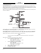
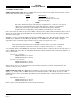
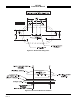
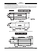
Table Of Contents

SKY497
Installation Manual
2-18
Rev. C
2.6.4 Heading Input Cable
The heading input cable connects the TRC497 to the aircraft heading system (refer to the Interconnect
Wiring Diagram, figure 2-2 or 2-3). This cable provides XYZ and HC aircraft heading information (or King
KCS55 stepper signals) to the TRC497. FLAG lines are also included in the heading input cable to provide
the TRC497 processor with flag status (or heading valid) information.
Figure 2-6 shows the TRC497 heading validation circuit of the King KCS55 that provides a heading valid
signal to the TRC497.
Figure 2-6. KCS55 Heading Flag Connection
If the heading source does not have a FLAG LO (-), the heading source FLAG HI(+) input is connected to
P1-53 (HDG_FLG+) and P1-52 (HDG_FLG-) is connected to ground.
If the heading system has a low level flag between 1.5 VDC and 2.7 VDC (when valid), P1-68 (HEADING
FLAG SENSE) should not be jumpered to ground and P1-53 (HDG_FLG+) must remain unconnected.
Table 2-8 lists some U.S. vendors who sell the required cable by the foot.
NOTE
Use of any cable not meeting BFG Avionics Systems specifications voids all system
warranties.
The synchro cable consists of the following (refer to figure 2-7):
1. Twisted, Shielded, Jacketed Triad #24 AWG
Colors: White, Blue, Orange
Shield: Tin Plated Copper Braid, 90% min.
Jacket: FEP .007 in. min., White
2. Twisted, Shielded, Jacketed Pair #24 AWG
Colors: White, Blue
Shield: Tin Plated Copper Braid, 90% min.
Jacket: FEP .007 in. min., Blue
3. Same as Item 2, except Orange jacket.
4. Aluminized Mylar
®
Wrap.
5. #34 AWG braided shield.