
Install Manual Part 2
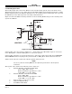
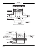
Table Of Contents

SKY497
Installation Manual
2-22
Rev. C
2.6.9 Ground Proximity Warning System (GPWS) Input
This input senses a GPWS alarm and temporarily disables the audio alert output until the warning clears.
The input can be either a constant flag signal or an alternating flag output. The flag must be cleared for
five (5) seconds before the TRC accepts a “NO ALARM” condition and restores audible alerts.
NOTES
1. If the aircraft is equipped with GPWS, it must be connected to the TRC.
2. If the aircraft is not equipped with GPWS, leave this input unconnected..
For the GPWS input (P1-32) line, use #22 AWG (minimum) unshielded cable. Routing and length are not
critical to system operation.
2.6.10 SKYWATCH/
Stormscope
Mode Switch
The SKYWATCH/Stormscope mode switch (SW1) is required only if a WX-1000 Stormscope Weather
Mapping System is installed. This switch permits the flight crew to switch the display between the
SKY497 and WX-1000. If a TA (Traffic Advisory) is detected in the Stormscope mode, the display will
switch to the SKYWATCH mode. Refer to figure 2-3 for interconnect wiring information. Any general
purpose SPST toggle switch (3 Amp @ 28 VDC) may be used. Display mode switch cable routing and length
are not critical to system operation. Mount the switch at a location easily accessible to the pilot.
2.6.11 WX-1000 Maintenance Switch
ON/OFF control and display brightness is controlled through the OFF/BRT switch located on the WX-1000
display. An external NORMAL/OVERRIDE control over-ride switch (SW2) is required only if a WX-1000
Stormscope Weather Mapping System is installed. The override switch enables the SKYWATCH to be
powered-up if the WX-1000 processor has been removed for maintenance. During normal operation the
switch should remain in the NORMAL position and moved to OVERRIDE only if the WX-1000 processor
has been removed for service or if it is necessary to access the WX-1000 service menu. Refer to figure 2-3
for interconnect wiring information. Any general purpose DPDT toggle switch (3 Amp @ 28 VDC) may be
used. The maintenance switch cable routing and length are not critical to system operation. The switch can
be located in the avionics bay near the WX-1000 processor.
2.6.12 Squat Switch Input
This signal line is to be connected to the squat switch to sense when the aircraft is on the ground. If the
aircraft is not equipped with a squat switch, it is recommended that a squat switch be installed.
For the SQUAT input (P1-88) line, use #22 AWG (minimum) unshielded cable. Routing and length are not
critical to system operation.
If a squat switch is not available, this input could be tied to an airspeed switch inline with the pitot system
as an alternate input for the squat switch. In this configuration care should be taken to ensure the switch
is set to trigger at a speed consistent with take-off and landing.
On helicopter installations with skids, and a squat switch is not available, this input can be tied to the
collective switch. In this configuration care should be taken to ensure the switch is connected to provide a
ground when the aircraft is on the ground and open when the aircraft is airborne.
If it is not possible to install a squat switch, airspeed switch, or collective switch ground this input. With
this configuration the pilot must press soft-key (4), labeled →
→→
→OPR or →
→→
→STB, to toggle the system in and
out of standby. To display traffic, the pilot will have to switch out of standby by pressing the →
→→
→OPR
button.
With a squat switch installed, SKYWATCH will automatically switch out of standby (i.e, ABV/6nm) 8 to 10
seconds after takeoff and switch back to standby 24 seconds after landing. A squat switch would also
prevent the pilot from placing SKYWATCH in standby (i.e., pressing the →
→→
→STB button) while the aircraft
is in-flight.