
Install Manual Part 2
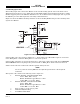
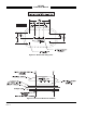
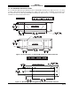
Table Of Contents

SKY497
Installation Manual
2-26
Rev. C
1. Position tray at the installation location.
2. Determine centers for mounting holes, and drill for required fasteners. See figure 2-10 (standard tray)
or 2-11 (ruggedized tray).
3. Secure tray in place using suitable 8-32 (channel mount) or 6-32 (flat mount) hardware.
2.9 TRC INSTALLATION
CAUTION
Before placing the TRC into its mounting tray, de-energize or disconnect all
power and signal sources and loads used with the SKY497 system.
1. Slide the TRC into the mounting tray (see figure 2-12). Ensure that the rear hold-down pins on the
mounting tray are properly inserted into receptacles on the TRC.
2. Place the retainer cups over the TRC J-hooks. Secure the TRC to the mounting tray by tightening the
self-locking hold-down knobs.
3. Connect the three antenna inputs to the connectors on the front panel.
a. Connect the Sum port antenna connector (P9 - a TNC connector identified with a blue band) to
connector J9 (identified with blue marking).
b. Connect the Probe (Bit) port antenna connector (P10 - a BNC connector identified with a black
band) to connector J10.
c. Connect the Difference (Delta) port antenna connector (P11 - a TNC connector identified with a
red band) to connector J11 (identified with red marking).
4. Connect I/O Signal Cable (P1 - a 100-pin connector) to connector J1.
5. Connect the power cable (P8 - a three pin connector) to connector J8.