
Install Manual Part 2
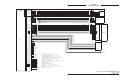
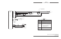

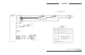
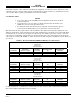
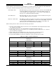
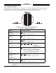
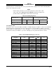
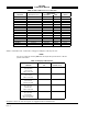
Table Of Contents

SKY497
Installation Manual
2-14
Rev. C
2.6.2 Configuration Jumpers
All installation dependent selections are defined via configuration jumpers. The configuration jumpers, as
detailed in table 2-3, are installed on the TRC mating connector (P1). Figure 2-4 shows the contact
arrangement for connector P1. Configuration ground is available at P1-12 and P1-13.
Figure 2-4. Connector P1 Contact Arrangement
Table 2-3. Configuration Jumpers
FUNCTION CONFIGURATION JUMPER
Airframe P1-98
Fixed Wing 1 (Open)
Rotor Craft 0 (Jumper to Configuration Ground)
Antenna P1-99
NY-164 1 (Open)
NY-156 0 (Jumper to Configuration Ground)
Antenna Position P1-100
Top 1 (Open)
Bottom* 0 (Jumper to Configuration Ground)
ARINC-429 Alternate Display P1-77 P1-78 P1-79 P1-80
None 1 1 1 1 (1 = Open)
ARINC 735 Type 1 Device** 1 1 1 0 (0 = Jumper to
Configuration Ground)
Heading Flag Sense P1-68
LOW 1 (1 = Open - If LOW level input on HDG_FLG+ (P1-53)
indicates valid heading or no valid heading input is
available or when ARINC 429 input is heading source.)
HIGH 0 (0 = Jumper to Configuration Ground - If HIGH level input on
HDG_FLG+ (P1-53) indicates valid heading.)
Heading Input Source P1-69 P1-70
None 1 1 (1 = Open)
Synchro 1 0 (0 = Jumper to Configuration Ground)
Stepper 0 1
ARINC 429 Bus 0 0
RS422 Interface P1-67
Data Recorder 1 (Open)
Alternate*** 0 (Jumper to Configuration Ground)
* See paragraph 2.3 Antenna Position
** ARINC-735 Type 1 device is a BFGAS designation that identifies the current display driver
*** Future Option