
Install Manual Part 3
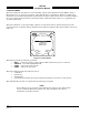
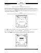
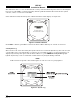
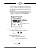
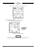
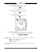
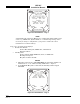
Table Of Contents
- CHAPTER 4- MAINTENANCE
- APPENDIX A - SIGNAL & CABLE CHARACTERISTICS
- APPENDIX B - CHECKOUT USING TCAS-201 RAMP TEST SET
- APPENDIX C - CHECKOUT USING T-49C FLIGHTLINE TESTER
- APPENDIX D - USING THE TERMINAL DEVICE
- APPENDIX E - CHECKOUT USING ALTERNATE DISPLAY

SKY497
Installation Manual
4-6
Rev. C
The buttons perform the following operations:
• EXIT - returns to the Service Menu (figure 4-1).
• SELECT - selects the highlighted item.
• PREV - steps to the previous item.
• NEXT - steps to the next item.
4.4.3.1 Software Version. The software version screen (see figure 4-7) identifies:
• IOP Code Version
• IOP Boot Version
• STP Code Version
• STP Boot Version
Software version can be accessed with a terminal device by using the Version command.
Figure 4-7. Software Version
NOTE
The software version identified on the TRC equipment tag represents the system software
configuration (i.e., a collective designator for all software/firmware installed within the
unit).
Press EXIT to return to the System Data screen. Soft-keys (2), (3) and (4) are not used.
4.4.3.2 Configuration. The configuration display consists of 4 pages. Configuration data on pages 1, 3 and 4
must be verified and saved on all new installations or if changes in configuration jumper(s) occur. The
buttons perform the following operations:
• EXIT - returns to the System Data Menu (figure 4-6).
• NEXT - steps to the next page.
• PREV - steps to the previous page.
• SAVE - saves configuration data for that page (not present if configuration jumpers
match configuration memory).
Configuration information can also be accessed with a terminal device by using the Config command.