
Install Manual Part 3
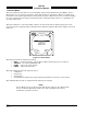
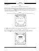
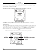
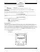
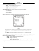
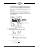
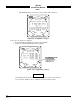
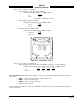
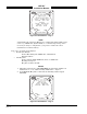
Table Of Contents
- CHAPTER 4- MAINTENANCE
- APPENDIX A - SIGNAL & CABLE CHARACTERISTICS
- APPENDIX B - CHECKOUT USING TCAS-201 RAMP TEST SET
- APPENDIX C - CHECKOUT USING T-49C FLIGHTLINE TESTER
- APPENDIX D - USING THE TERMINAL DEVICE
- APPENDIX E - CHECKOUT USING ALTERNATE DISPLAY

SKY497
Installation Manual
4-9
Rev. C
Page 3 of 4 (see figure 4-10) displays:
• Antenna Position (Ant. Pos.: TOP or BOT)
Configuration Jumper P1-100 (OPEN or GND)
P1-100
Top OPEN
Bottom* GND
*See paragraph 2.3 (ANTENNA LOCATION)
• Antenna Type (NY164 or NY156)
Configuration Jumper P1-99 (OPEN or GND)
P1-99
NY164 OPEN
NY156 GND
• Airframe (Ant. Pos.: FIX or ROT)
Configuration Jumper P1-98 (OPEN or GND)
P1-98
Fixed Wing OPEN
Rotorcraft GND
Figure 4-11. Configuration - Page 4
Page 4 of 4 (see figure 4-11) displays:
• Alternate Display Type (None Selected, ARINC 735 Type 1, or Illegal Display)
Configuration Jumpers P1-77, P1-78, P1-79 & P1-80 (OPEN or GND)
P1-77 P1-78 P1-79 P1-80
None OPEN OPEN OPEN OPEN
735 Type 1 OPEN OPEN OPEN GND
4.4.3.3 Data Monitor. The data monitor display consists of 5 pages. The buttons perform the following
operations:
• EXIT - returns to the System Data Menu (figure 4-6).
• NEXT - steps to the next page.
• PREV - steps to the previous page.
• Soft-key (4) is not used.
The data monitor information can be accessed with a terminal device by using the Bar, Head, Rad and
Config commands.