
User guide

VIII. ASSEMBLY INSTRUCTIONS, SPECIFICATIONS AND PARTS SELECTION
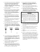
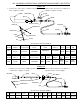
Model 156
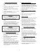
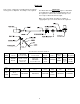
Model 162
Specifications and Part Numbers
Heat Operating Pilot Pilot
Model Output Pressure/Fuel Torch Head Orifice Screen Sleeve Nut
250,000 25 PSIG Cast Iron 130-
BTUH LP Vapor 320-03989 01722
Pilot Burner Pilot Manual Pilot Safety
Bracket Orifice Tube Thermocouple Valve Valve Adapter Hose Adapter Regulator
400- 310- 410- 130- 130- 310- 310-
03202 01329 20529 20229 07966 07970 01098
5
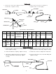
1. Connect one end of hose to adapter at torch
inlet. Tighten securely.
2. Connect other end of hose to adapter at
regulator. Tighten securely.
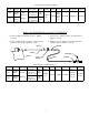
1. Connect one end of hose adapter at inlet of
needle valve. Tighten securely.
2. Connect other end of hose to adapter at
regulator outlet. Secure tightly.
156 400-01079 310-01230
130-
02542
130-
02543
120-05864
550-
21788
550-
20703
1/4 in. ID
x 10 ft.
ADAPTER
REGULATOR
VALVE, MANUAL
HANDLE
ADAPTER
NIPPLE
NIPPLE
HOSE
ORIFICE
VALVE, SAFETY
TORCH HEAD
THERMOCOUPLE
THERMOCOUPLE BRACKET
BURNER
ORIFICE
VALVE, MANUAL
NUT
SLEEVE
ELBOW
ADAPTER
VALVE, PILOT SAFETY
REGULATOR
ADAPTER
HOSE
THERMOCOUPLE
HEAD, PILOT
BRACKET, PILOT
SCREEN
TUBE
NUT
SLEEVE
ORIFICE, PILOT
130-
01108
400-01094
130-
20229
310-
01098
130-
01142
162
25 PSIG
LP Vapor
Operating
Pressure/Fuel
310-
03416
Specifications and Part Numbers
Heat Torch Manual Hose Safety Thermo-
Thermocouple
Model Output Head Handle Orifice Nipple Valve Adapter Hose Regulator Valve couple Bracket
400,000
Cast Iron, 320-03432
330-05169 550-20703 550-21788 30 in.
BTUH
2 3/8 in. OD x 7 in.
11 in. 1/4 in. x 10 ft. 25 PSIG 120-01020