Owner's Manual and Instructions GUARDIAN ® Agricultural Animal Confinement Building Heaters with Smart Sense™ Automatic Variable Rate Heat For Direct Connection to a Building Controller View this manual online at www.lbwhite.com MODELS OUTPUT (Btuh) AD060 60,000 AD100 100,000 FUEL Propane-Vapor Withdrawal and Natural Gas Patent Pending SCAN THIS QR CODE Congratulations! with your smartphone or visit http://goo.gl/nksqZ to view maintenance videos for L.B.White heaters.
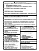
GENERAL HAZARD WARNING ■ Failure to comply with the precautions and instructions provided with this heater, can result in: — Death — Serious bodily injury or burns — Property damage or loss from fire or explosion — Asphyxiation due to lack of adequate air supply or carbon monoxide poisoning — Electrical shock ■ Read this Owner’s Manual before installing or using this heater. ■ Only properly-trained service people should repair or install this heater. ■ Save this Owner’s Manual for future use and reference.
Table of Contents PAGE SECTION General Information . . . . . . . . . . . . . . . . . . . . . . . . . . . . . . . . . . . . . . . . . . . . . . . . . . . . . . . . . . . . . . . . . . .3 Heater Specifications . . . . . . . . . . . . . . . . . . . . . . . . . . . . . . . . . . . . . . . . . . . . . . . . . . . . . . . . . . . . . . . . . .4 Basic Operation . . . . . . . . . . . . . . . . . . . . . . . . . . . . . . . . . . . . . . . . . . . . . . . . . . . . . . . . . . . . . . . . . . . . . .
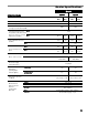
Heater Specifications Model SPECIFICATIONS AD060 AD100 Propane Natural Gas Gas Propane Natural Gas Gas 60,000 15,000 100,000 25,000 240 400 Maximum Input (BTUH) Minimum Input (BTUH) Ventilation Air Required to Support Combustion (CFM) Inlet Gas Supply Pressure MAX. Acceptable at the Inlet of the Heater for Purpose of Input MIN. Adjustment ( In.W.C.) Burner Manifold Pressure MAX. (In.W.C.) MIN. Fuel Consumption Per Hour 13.5 11.0 10.0 11.0 10.0 10.0 9.0 10.0 9.0 0.8 0.5 MAX. 2.78 lbs.
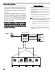
Basic Operation This heater uses Smart Sense™ technology for variable rate heat control. L.B.White has worked with agricultural building control manufacturers for the proper implementation of the Smart Sense™ variable rate heating control logic. If you have questions on whether or not your control incorporates the Smart Sense™ control logic, call L.B.White Co. Sequence of Operation a. Building controller determines that heat is required. b.
Safety Precautions WARNING Asphyxiation Hazard ■ Do not use this heater for heating human living quarters. ■ Do not use in unventilated areas. ■ The flow of combustion and ventilation air must not be obstructed. L.B. White Company to determine combustion air ventilation requirements of the heater. ■ Lack of proper ventilation air will lead to improper combustion. ■ Proper ventilation air must be provided to support the combustion air requirements of the heater being used.
1. Do not attempt to install, repair, or service this heater or the gas supply line unless you have continuing expert training and knowledge of gas heaters. Never operate this heater with any safety device that has been bypassed. Do not operate this heater unless all of these features are fully functioning. Qualifications for service and installation of this equipment are as follows: 6. Do not operate the heater with its door open or panel removed. a.
Installation Instructions GENERAL WARNING Fire or explosion hazard. Can cause property damage, severe injury or death. 1. Disconnect power supply before wiring to prevent electrical shock or equipment damage. 2. To avoid dangerous accumulation of fuel gas, turn off gas supply at the appliance service valve before starting installation, and perform gas leak test after completion of installation. 3. Do not force the gas control knob. Use only your hand to turn the gas control knob. Never use any tools.
12. A qualified service agency must check for proper operating gas pressure upon installation of the heater. 13. Light according to instructions on heater or within owner's manual. 14. It is extremely important to use the proper size and type of gas supply line to assure proper functioning of the heater. Contact your fuel gas supplier for proper line sizing and installation. 15. This heater can be configured for use with either L.P. gas vapor withdrawal or natural gas.
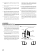
HANGING INSTRUCTIONS 1. Assemble according to the illustration and tighten all eyebolts securely. See Fig. 3. NOTE: REGULATORS SHOULD ALWAYS BE MOUNTED OUTDOORS. IF NOTE: REGULATORSFORCE SHOULDINSTALLING ALWAYS BE MOUNTED OUTDOORS. IFINDOORS, CIRCUMSTANCES THE REGULATOR CIRCUMSTANCES FORCE INSTALLING THE REGULATOR INDOORS, THE REGULATOR’S VENT MUST BE VENTED OUTDOORS USING VENT THE REGULATOR'S VENT MUST BE VENTED OUTDOORS USING VENT LINE NOLINE SMALLER THAN VENT NO SMALLER THAN VENTOPENING. OPENING. FIG.
MANUAL SHUT-OFF VALVE, HOSE AND REGULATOR ASSEMBLY 1. Always use approved pipe thread compound suitable for use with L.P. gas or natural gas on the threaded connections. FIG. 6 VALVE, MANUAL SHUT-OFF 2. Assemble the components together according to the figure. This view is to show general assembly of the components only. The regulator must always be mounted so its vent, regardless of location on the regulator, is always pointed downward. NIPPLE REGULATOR 4.
INTERCONNECTION FOR VARIABLE HEAT ■ The Smart Sense™ variable rate heater incorporates a signal conditioner board in the control box. This signal conditioner takes the control signal supplied from the building controller and provides the necessary power to control the variable rate gas control valve. ■ When interconnecting the building controller to the signal conditioner: FIG. 8 -- Use customer supplied 1/4 insulated female terminals.
Start-Up Instructions Follow steps 1 - 6 on initial start-up after heater installation by a qualified gas heater service person. For normal startup, set the building controller to call for heat. The heater will start. 1. Open all manual fuel supply valves and check for gas leaks using approved leak detectors. 2. Connect the electrical cord to an approved electrical outlet. 3. Set the building controller to desired room temperature. 4.
Cleaning Instructions WARNING Fire, Burn, and Explosion Hazard ■ This heater contains electrical and mechanical components in the gas management, safety and airflow systems. ■ Such components may become inoperative or fail due to dust, dirt, wear, aging, or the corrosive atmosphere of an animal confinement building. ■ Periodic cleaning and inspection as well as proper maintenance are essential to avoid serious injury or property damage. 1.
Service Instructions GENERAL WARNING Burn Hazard ■ Heater surfaces are hot for a period of time after the heater has been shut down. ■ Allow the heater to cool before performing service, maintenance, or cleaning. ■ Failure to follow this warning will result in burns causing injury. WARNING Fire and Explosion Hazard ■ Do not disassemble or attempt to repair any heater components or gas train components. ■ All component parts must be replaced if defects are found.
AIR PROVING SWITCH WITH PADDLE The air proving switch must work properly to allow an ignition cycle. If the air proving switch contacts do not close on a call for heat after the fan motor starts, ignition will not occur. FIG. 13 1. Remove the two (2) sheet metal screws holding the switch with bracket to blower housing. See Fig. 13. 2. Remove the assembly by turning the switch so the paddle on the switch arm can be pulled through the oblong hole on side of fan housing.
TESTING THE MANUAL RESET HIGH LIMIT SWITCH WARNING Fire Hazard ■ Do not operate the heater with the high limit switch bypassed. ■ Operating the heater a bypass high limit switch may lead to overheating, possibly resulting in a fire, with subsequent damage to the heater, building damage, or loss of livestock. This heater uses a high limit heat switch for the purpose of over heat protection.
Gas Pressure Checks ■ The following explains a typical procedure to be followed 3. Open the fuel supply valves to the heater and reconnect the heater electrical supply. ■ Consult the dataplate on the heater or page 4 in this 4. Start the heater in checking gas pressures. manual for specific pressures to be used in conjunction with this procedure. ■ Gas pressure entering the gas valve is Inlet Pressure. Gas pressure flowing out of the gas valve is Burner Manifold pressure. C. Reading Pressures 1.
Troubleshooting Instructions READ THIS ENTIRE SECTION BEFORE BEGINNING TO TROUBLESHOOT PROBLEMS. WARNING Electrical Shock and Burn Hazard ■ Troubleshooting this system may require operating the unit with line voltage present and gas on. Use extreme caution when working on the heater. ■ Failure to follow this warning may result in property damage, personal injury or death. The troubleshooting flow charts on the following pages provide systematic procedures for isolating equipment problems.
OPERATION SEQUENCE: — A call for heat occurs from the building controller. — 115 VAC is sent to: -- 40 VA transformer and to ignition control -- 20 VA transformer — 20 VA transformer reduces line voltage to 24 VAC. -- 24 VAC is sent to operate signal conditioner — 0-10 VDC, 0-20 mA, or 4-20 mA signal is sent to signal conditioner from building controller. — Signal conditioner changes the building controller input signal to 0-15 VDC which is sent to variable rate gas control valve.
21 Connect it to the power supply. No No Is proper voltage supplied to heater power cord and through power cord? Set the building controller to call for heat. No Is building controller calling for heat? Yes Yes Is airproving switch shorted? (Perform continuity check on airproving switch.
22 Air proving switch does not close during a call for heat. Two Times Yes No Are 24 volts sent to air proving switch? Yes Defective motor or capacitor. Check wiring between ignition control module terminal PS1 and and air proving switch. Repair or replace as necessary. If wiring is good replace ignition control. Yes If improper voltage is supplied, contact electrician. - OR If no voltage is supplied to motor, check wiring, or replace ignition control module.
If pressure is not read, check ohm reading between wires of recitifier plug as connected to gas control. Reading should be 3 meg ohm. If reading shows overload or 0 ohms, replace the rectifier plug and recycle the heater. If problem still exists, replace the gas control valve. No Yes Yes Remove orifice and burner casting. Blow out with compressed air or clean with a soft brush.
24 If ignition control module does not reset, then replace the control. (Internal fault.) If ignition control module resets, then have qualified electrician check power source for power quality problems. (Frequency, line noise, line spikes, loose connections, too small wire gauge.) Ignition control is identifying a flame sense related problem. Burner flame failure may occur. Check all grounds, clean the sensor or check for cracks in sensor insulator.
Electrical Connection and Ladder Diagram + 1 2 6 7 5 3 + 25
Heater Component Function Air Proving Switch Safety device used to insure that the proper air flow is being achieved before the gas valve is opened. Burner Cast iron component used to channel gas and provide an area at which the fuel may ignite. Burner Orifice Brass metering device used to feed gas to burner at a specific rate. Igniter/Flame Sensor Assembly This assembly consists of two components mounted adjacent on the same bracket.
Parts Identification PARTS SCHEMATIC 27
Parts Identification PARTS LIST Item 1 2 3 4 5 6 Description Regulator, 2nd stage, vent over outlet Regulator, 2nd stage, vent over side Regulator, 2nd stage, with vent limiter Valve, manual shut off with nipple Hose, 1/2 in. ID x 10 ft.
Item 32 Description Door, burner end 33 Door , motor end 34 35 Liquid tight connector, 3/8 in., with nut and washer Liquid tight connector, 1/2 in., with nut and washer 60,000 btuh Propane Gas 100,000 btuh Propane Gas 60,000 btuh Propane Gas 100,000 btuh Propane Gas 60,000 btuh Natural Gas 100,000 btuh Natural Gas Part Number 573155 573156 573223 573222 573221 573220 573233 22571 Warranty Policy HEATER L.B. White Co., Inc.