Owner’s Manual and Instructions Spark Ignition Infraconic Agricultural Building Radiant Heaters MODELS I17 OUTPUT (Btuh) 17,100 FUEL Propane Vapor Withdrawal or Natural Gas Congratulations! You have purchased the finest radiant heater available for the heating of livestock in agricultural animal confinement buildings. Your new L.B. White radiant heater incorporates the benefits from the most experienced manufacturer of heating products using state-of-the-art technology. We, at L.B.
GENERAL HAZARD WARNING ■ Failure to comply with the precautions and instructions provided with this heater, can result in: — Death — Serious bodily injury or burns — Property damage or loss from fire or explosion — Asphyxiation due to lack of adequate air supply or carbon monoxide poisoning — Electrical shock ■ Read this Owner’s Manual before installing or using this heater. ■ Only properly-trained service people should repair or install this heater. ■ Save this Owner’s Manual for future use and reference.
Table of Contents SECTION PAGE General Information . . . . . . . . . . . . . . . . . . . . . . . . . . . . . . . . . . . . . . . . . . . . . . . . . . . . . . . . . . . . . . . . . . .3 Heater Specifications . . . . . . . . . . . . . . . . . . . . . . . . . . . . . . . . . . . . . . . . . . . . . . . . . . . . . . . . . . . . . . . . . .4 Safety Precautions . . . . . . . . . . . . . . . . . . . . . . . . . . . . . . . . . . . . . . . . . . . . . . . . . . . . . . . . . . . . . . . . . . . .
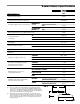
Radiant Heater Specifications Model I17 SPECIFICATIONS Maximum Input (Btuh) 17,100 200 CFM Ventilation Air to Support Combustion FULL OUTPUT Inlet Gas Supply Pressure at the Heater (On/Off Version) ZONE CONTROLLED (Dual Solenoid Version) MAX. 5 psig MIN. 5 psig MAX. 5 psig MIN. 2 psig Burner Manifold Pressure at Maximum Pressure Heater Dimensions (See Fig. 1) 5 psig “A” 16-5/8 in. “B” 14 in. “C” 6 3/4 in. Net Weight Fuel Consumption Per Hour 9 lbs. 2 oz. PROPANE GAS .80 lbs./hr.
Safety Precautions WARNING Asphyxiation Hazard ■ Do not use this radiant heater for heating human living L.B. White Company to determine combustion air quarters. ventilation requirements of the heater. ■ Do not use in unventilated areas. ■ The flow of combustion and ventilation air must not be obstructed. ■ Lack of proper ventilation air will lead to improper combustion. ■ Proper ventilation air must be provided to support the combustion air requirements of the heater being used.
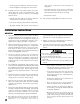
Safety Precautions 1. Do not attempt to install, repair or service this heater or the gas supply line unless you have continuing expert training and knowledge of gas heaters. Qualifications for service and installation of this equipment are as follows: QUALIFICATIONS FOR SERVICING AND INSTALLATION: a.
-- Check for general cleanliness. Clean if necessary. inlet venturi, combustion cones and filter (if applicable). -- Check for tightness of the gas hose connections. -- Thorough inspection of the heater’s component parts for corrosion, stripped threads, etc. with subsequent parts replacement as necessary. 14. A qualified service person shall inspect the heater and its gas train at least on an annual basis.
-- If a leak is detected, check the components involved for cleanliness in the thread areas and proper application of pipe compound before further tightening. 14. -- Tighten the gas connection as necessary to stop the leak. -- If necessary, replace the parts or components involved if the leak cannot be stopped. 15. The corrosive atmosphere present in animal confinement buildings can cause component failure or heater malfunction.
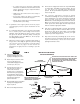
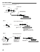
GAS TRAIN ASSEMBLY This heater is supplied with one of the following gas train assemblies. Refer to the appropriate illustrations. FIG. 3 STANDARD HOSE BUSHING RIGID END OF HOSE TO GAS SUPPLY CONNECT HOSE TO GAS INLET, TIGHTEN SECURELY VALVE, SHUT-OFF FIG. 4 1/8 NPT FITTING KIT, PART #23406 A B STEM FITTING ASSEMBLY NUT CONTROL VALVE INLET - ASSEMBLE FITTING - ATTACH FITTING TO GAS INLET & TIGHTEN SECURELY. - CONNECT APPROVED GAS HOSE ASSEMBLY WITH APPROPRIATE CONNECTIONS TO 1/8 NPT FITTING.
ZONE CONTROL PANEL FUNCTION AND INSTALLATION (Optional) The zone control panel is a remote mounted control system allowing the operation of a specific amount of heaters within a certain zone of the building. These panels will control the following quantity of heaters depending on fuel type. Solenoid Zone Control System Fuel Medium Capacity Panel High Capacity Panel I17 L. P.
Start-Up Instructions Follow steps 1-5 on initial start up after heater installation by a qualified gas heater service person. For normal startup, simply turn the building thermostat above room temperature. 1. Connect the heater to an approved electrical supply and building’s temperature control system. 2. Open all gas supply valves to the heater and check for gas leaks at all connections using approved leak detectors. 3.
Cleaning Instructions 5. Inspect the cones and venturi tube to make sure these areas are clean. It is important to clean the heater and the optional dust filter on a regular basis to maintain proper combustion and to eliminate future problems. Do not clean the heater with water or other liquids. The frequency of cleaning will var y depending upon livestock being raised and overall ventilation of the building. 6. Return the heater to its normal hanging position and relight the heater. FIG.
Maintenance Instructions 1. Have your gas supplier check all gas piping annually for leaks or restrictions in gas lines. Also, at this time have your gas supplier clean out the sediment trap on the zone control panel of any debris that may have accumulated. 2. The heater’s surrounding area shall be kept clear and free from combustible materials, gasoline, and other flammable vapors and liquids. 3. Regulators can wear out and function improperly.
ON/OFF SWITCH 1. Remove control box screws and cover. FIG. 9 2. Disconnect the electrical leads from the ON/OFF switch. 3. Remove the rubber boot from the ON/OFF switch. See Fig. 9. Remove the switch from the control box. BOOT IGNITION MODULE ■ Handle the module at the edges of the board ■ Don’t touch or allow contact to the module FIG. 10 IGNITION CABLE components, otherwise damage may occur. 1. Remove control box screws and cover. 2.
HIGH VOLTAGE IGNITION CABLE 1. Remove the control box cover. FIG. 13 2. Disconnect the igniion cable from ignition module. B 3. Loosen the water tight connector nut. See Fig. 12. Pull the ignition lead through this connection. 4. Disconnect the high voltage ignition cable from the ignitor. See Fig. 13.
BURNER COMBUSTION CONES and GASKET Very little servicing is required for the combustion cones and gasket. Routine cleaning is sufficient to ensure that the cones remain unblocked by dust and dirt. Periodic tightening of the the three burner plate nut ensures that the heater operates to normal combustion characterisitics. FIG. 18 TIP WELD SEAM If not cleaned, the venturi tube and inner combustion cone will become blocked, creating poor combustion, gas backflashing through the air housing, or outages.
GAS CONTROL VALVE 1. Loosen the jam nut at the air housing. Ensure o-ring is seated in jam nut. 2. Loosen the water tight connector nut at the control box securing the control valve’s wiring. 3. Remove the control box cover and disconnect the valve’s wiring from the ignition control. -- Thread the jam nut hand tight against the body of the control and secure in place with a wrench. FIG. 20 LOOSEN CONNECTOR REMOVE SCREW 4.
Troubleshooting Guide READ THIS ENTIRE SECTION BEFORE BEGINNING TO TROUBLESHOOT PROBLEMS. The following troubleshooting flow charts provide systematic procedures for isolating heater problems. The charts are intended for use by a QUALIFIED GAS HEATER SERVICE PERSON. DO NOT SERVICE THE HEATER UNLESS YOU HAVE BEEN PROPERLY TRAINED. Components should be replaced only after each step has been completed and replacement is suggested in the flow chart.
19 No Are all fuel supply valves open? Yes Check for voltage and resistance of switch and electrical leads between switches and ignition control. Replace if defective. No Yes A. Check igniter for defects, cleanliness, and proper gap. B. Check ignition lead. Verify resistance of lead. Should be 1 ohm or less. Ensure lead has good connections and no cuts. Replace if necessary. C. If igniter and ignition lead are good, Replace inition control. No Yes Yes Yes Replace ignition control.
20 Heater backflashes gas through air inlet. Problem 3 Heater lights but will not stay lit Problem 2 Yes No Is high voltage ignition lead in good condition? Yes Check for proper gas pressure. Proper pressure at high heat should read 5 PSIG.
Electrical Connection and Ladder Diagram CAUTION: REFER TO THE HEATER'S ELECTRICAL CONNECTION DIAGRAM WHEN SERVICING TO AVOID WIRING ERRORS AND HEATER MALFUNCTION. CHECK FOR PROPER OPERATION AFTER SERVICING.
Heater Component Function Air Housing Allows combustion air to be drawn in to venturi tube with gas flow for combustion. Burner Orifice Metering device used to feed gas to combustion cones at a specific flow rate. Canopy Reflective aluminum heat shield for heater. Double Combustion Chamber Made of special alloy steel. This is where combustion of gas occurs, providing radiant heat used in the warming process.
Parts Identification PARTS SCHEMATIC 23 23
PARTS LIST Item 1 2 2A 2B 2C 3 4 5 6 7 8 9 10 11 Description Venturi tube and burner assembly Kit, combustion cones with gasket Gasket Inner cone Outer cone Hardware for burner plate (nuts, screws, spacers, 3 each) Burner plate with hardware Truss clip Ignitor with screws Key Ring Adapter Jam nut Solenoid valve with adapters Air housing assembly, with orifice, jam not, and register plate 12 Orifice,burner 13 13A 13B 14 Filter Kit Filter Filter sleeve Control box with cover , and bracket 15 16 17 18 19
Warranty Policy EQUIPMENT L.B. White Co., Inc. warrants that the component parts of its equipment are free from defects in material and workmanship, when properly installed, operated, and maintained in accordance with the Installation and Maintenance Instructions, safety guides and labels contained with each unit. If, within 12 months from the date of purchase by the end user, any component is found to be defective, L.B. White Co., Inc.