Owner’s Manual and Instructions Spark Ignition Infraconic Agricultural Building Radiant Heaters MODELS OUTPUT (Btuh) I17 17,100 I34 34,200 FUEL L.P. Vapor Withdrawal or Natural Gas Congratulations! You have purchased the finest radiant heater available for the heating of livestock in agricultural animal confinement buildings. Your new L.B. White radiant heater incorporates the benefits from the most experienced manufacturer of heating products using state-of-the-art technology. We, at L.B.
GENERAL HAZARD WARNING ■ Failure to comply with the precautions and instructions provided with this brooder, can result in: — Death — Serious bodily injury or burns — Property damage or loss from fire or explosion — Asphyxiation due to lack of adequate air supply or carbon monoxide poisoning — Electrical shock ■ Read this Owner’s Manual before installing or using this product. ■ Only properly-trained service people should repair or install this brooder.
Table of Contents PAGE SECTION General Information . . . . . . . . . . . . . . . . . . . . . . . . . . . . . . . . . . . . . . . . . . . . . . . . . . . . . . . . . . . . . . . . . . .3 Heater Specifications . . . . . . . . . . . . . . . . . . . . . . . . . . . . . . . . . . . . . . . . . . . . . . . . . . . . . . . . . . . . . . . . . .4 Safety Precautions . . . . . . . . . . . . . . . . . . . . . . . . . . . . . . . . . . . . . . . . . . . . . . . . . . . . . . . . . . . . . . . . . . . .
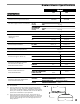
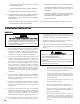
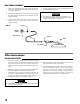
Radiant Heater Specifications Model I17 I34 Maximum Input (Btuh) 17,100 34,200 Ventilation Air to Support Combustion 200 CFM 400 CFM SPECIFICATIONS Inlet Gas Supply Pressure at the Heater FULL OUTPUT (On/Off Version) ZONE CONTROLLED (Dual Solenoid Version) MAX. 5 psig MIN. 5 psig MAX. 5 psig MIN. 2.5 psig Burner Manifold Pressure at Maximum Pressure Heater Dimensions (See Fig. 1) 5 psig “A” 16 7/8 in. 26 3/8 in. “B” 17 in. 20 1/4 in. “C” 8 3/4 in. 10 3/8 in.
Safety Precautions WARNING Asphyxiation Hazard ■ Do not use this radiant heater for heating human living L.B. White Company to determine combustion air quarters. ventilation requirements of the heater. ■ Do not use in unventilated areas. ■ The flow of combustion and ventilation air must not be obstructed. ■ Lack of proper ventilation air will lead to improper combustion. ■ Proper ventilation air must be provided to support the combustion air requirements of the heater being used.
Safety Precautions 1. Do not attempt to install, repair or service this heater or the gas supply line unless you have continuing expert training and knowledge of gas heaters. Qualifications for service and installation of this equipment are as follows: QUALIFICATIONS FOR SERVICING AND INSTALLATION: a.
-- Insure proper clearance of heater to nearest combustible materials. -- Leak check of all pipe joints and hose connections. -- Thorough cleaning of the exterior of the heater, its inlet venturi, combustion cones and filter (if applicable). -- Check for general cleanliness. Clean if necessary. -- Check for tightness of the gas hose connections. -- Thorough inspection of the heater’s component parts for corrosion, stripped threads, etc. with subsequent parts replacement as necessary. 14.
-- If a leak is detected, check the components involved for cleanliness in the thread areas and proper application of pipe compound before further tightening. for information on gas pressures relating to specific models. 12. The heater is designed for either L.P. vapor withdrawal or natural gas, depending on model number. Do not use this heater in an LPG liquid withdrawal system. Do not permit LPG in liquid form to enter the heater at any time. -- Tighten the gas connection as necessary to stop the leak.
GAS TRAIN ASSEMBLY 1. Thread the bushing into one end of manual shut off valve. Use pipe thread compound at this connection and tighten securely. 2. Thread the rigid end of the hose into the bushing. Use pipe thread compound at this connection and tighten securely. 3. Thread other end of gas hose with fitting to the adapter at inlet of gas control valve on heater. Tighten securely. 4. Connect the gas supply to inlet of manual gas shut off as required by local codes.
CLEANING THE FILTER (Frequency of cleaning will depend upon livestock being raised and overall condition of the building.) ATTENTION CAUTION ■ Never allow the filter to become fully clogged with dust and dirt. operation. ■ A dust choked filter will restrict the combustion air, causing improper combustion.
Start-Up Instructions Follow steps 1-5 on initial start up after heater installation by a qualified gas heater service person. For normal startup, simply turn the building thermostat above room temperature. 1. Connect the heater to an approved electrical supply and building’s temperature control system. 2. Open all gas supply valves to the heater and check for gas leaks at all connections using approved leak detectors. 3.
Cleaning Instructions It is important to clean the heater on a regular basis to maintain proper combustion and to eliminate future problems. The frequency of cleaning will var y depending upon livestock being raised and overall ventilation of the building. ATTENTION Combustion problems associated with lack of cleaning typically are: ■ Sooting on inside of canopy. ■ Burner flame appearing beyond outer cone. CLEANING WITH BACKPACK BLOWERS AND HEATER BLOWER Blower Part No.
Maintenance Instructions 1. Have your gas supplier check all gas piping annually for leaks or restrictions in gas lines. Also, at this time have your gas supplier clean out the sediment trap on the zone control panel of any debris that may have accumulated. 2. The appliance area shall be kept clear and free from combustible m aterials, g asoline, a nd o ther flammable vapors and liquids. 3. Regulators can wear out and function improperly.
ON/OFF SWITCH 1. Disconnect the heater from its electrical supply. FIG. 7 2. Close fuel supply valves to heater.. BOOT 3. Remove filter and filter sleeve (if applicable). Remove the screws that secure the control box cover to the control box and lift cover from box. 4. Disconnect the electrical leads from the ON/OFF switch. 5. Using the appropriate wrench, remove the rubber boot from the ON/OFF switch. See Fig. 7. SWITCH 6. Remove the switch from the control box. 7.
HIGH VOLTAGE IGNITION LEAD 1. Disconnect heater from its electrical supply. 2. Close fuel supply valves. 3. Remove filter and filter sleeve. 4. Remove the control box cover. 10. Remove the connector nut from the ignition cable. This same nut will be slid over the replacement ignition cable and used to create a water tight connection at the control box. Tighten the nut securely. ATTENTION 5. Disconnect the igniter lead from ignition module. 6.
IGNITER/FLAME SENSOR 1. Disconnect the heater from its electrical supply. ATTENTION 2. Close fuel supply valves to heater. ■ To adjust igniter gap, remove outer combustion cone. 3. Pull the boot of the ignition lead up and back from the igniter along the lead to expose the igniter to ignition lead terminal. If the ignition cable terminal disconnects as the boot is being pulled back, use a needle nose pliers to retrieve the terminal and pull it back through the igniter end of the boot. See Fig. 11.
HIGH LIMIT SWITCH ATTENTION ■ This heater is equipped with a manual reset high limit switch. Its purpose is to disconnect the electrical supply to the ignition control board in the event of an overheat condition. ■ An overheat condition is normally caused by: -- Excessive fuel gas pressure -- Heater not being routinely cleaned -- Heater not properly hung. (Control end is 1º to 5º down from horizontal. See page 8.
GAS PRESSURE CHECKS 1. Connect the pressure test kit hose to the fitting at the inlet of the gas control valve. Tighten securely. See Fig. 15. WARNING Fire and Explosion Hazard ■ Do not disassemble the gas control valve. ■ Do not attempt to replace any components on the gas control valve. ■ The gas control valve must be replaced if any physical damage occurs to the control valve assembly. 2. Connect the gas supply hose to the hose fitting on the test kit. Tighten securely. See Fig. 15. 3.
Troubleshooting Guide READ THIS ENTIRE SECTION BEFORE BEGINNING TO TROUBLESHOOT PROBLEMS. The following troubleshooting flow charts provide systematic procedures for isolating heater problems. The charts are intended for use by a QUALIFIED GAS HEATER SERVICE PERSON. DO NOT SERVICE THE HEATER UNLESS YOU HAVE BEEN PROPERLY TRAINED. Components should be replaced only after each step has been completed and replacement is suggested in the flow chart.
20 Heater Does Not Light Problem 1 Yes Provide Proper Voltage to Power Cord. - Check Circuit Breakers - Make sure building environment control thermostat is working properly and calling for heat No Is Proper Voltage Supplied to Heater Power Cord? No Replace Ignition Control According to Instructions in this Owner’s Manual Is Proper Voltage Supplied to Solenoid Valve on Heater? Check all Leads of Power Cord for Resistance. Replace Power Cord if Necessary.
21 Heater Lights but will not Stay Lit Problem 2 Yes Verify Resistance Value of Cable. Should be 5-7K OHM. Verify Cable has Good Connections. Repair or Replace if Necessary.
22 Heater Burner Flame Extends Beyond Outer Burner Cone or Black Soot on Inside of Canopy Problem 3 Remove Air Filter and Clean According to Prescribed Methods in this Owner’s Manual. No Is Dust Filter Clean? Yes Check Gas Pressure to the Brooder Inlet with a Gas Gauge. Proper Pressure Should Read 5 PSIG.
Electrical Connection and Ladder Diagram CAUTION: REFER TO THE HEATER'S ELECTRICAL CONNECTION DIAGRAM WHEN SERVICING TO AVOID WIRING ERRORS AND HEATER MALFUNCTION. CHECK FOR PROPER OPERATION AFTER SERVICING.
Heater Component Function Burner Orifice Metering device used to feed gas to combustion cones at a specific flow rate. Ignition Control Module Electronic device which controls the ignition sequence and operation of the heater. Double Combustion Chamber Made of special alloy steel. This is where combustion of gas occurs, providing radiant heat used in the warming process. Injector Body Allows combustion air to be drawn in to injector tube with gas flow for combustion.
Parts Identification PARTS SCHEMATIC 10 9 11 37 34 5 30 35 25 32 27 4 23 26 28 8 22 24 6 31 31A 31B 12 2 1 20 29 3 7 16 1 41 17 36 40 42 39 38 21 14 13 18 33 19 25
PARTS LIST Item 1 Description 25 Inner Cone Outer Cone Combustion Cone Kit with Gasket Gasket Plate, Burner Igniter Cover, Igniter Mounting Spacer Screw 10-32 x 1 1/2 Nut 10-32 Chain Assembly Key Ring Link, Chain Adjustment Clip, Chain Hanging Lead, Igniter w/ Boot Connector, Liquid Tight Control, Direct Spark Ignition Switch, On/Off Boot, On/Off Switch Bracket, Control Box Control Box Cover w/ Gasket Control Box Bottom Bushing Adapter, Hose Valve, Gas Control w/ Electrical Leads and Screen Orifice, Burn
Warranty Policy EQUIPMENT L.B. White Co., Inc. warrants that the component parts of its equipment are free from defects in material and workmanship, when properly installed, operated, and maintained in accordance with the Installation and Maintenance Instructions, safety guides and labels contained with each unit. If, within 12 months from the date of purchase by the end user, any component is found to be defective, L.B. White Co., Inc.