Owner’s Manual and Instructions Infraconic Agricultural Building Radiant Heaters Manual Ignition MODEL OUTPUT (Btuh) FUEL I17 17,100 Propane Vapor Withdrawal or Natural Gas Congratulations! You have purchased the finest radiant heater available for the heating of livestock in agricultural animal confinement buildings. Your new L.B. White radiant heater incorporates the benefits from the most experienced manufacturer of heating products using state-of-the-art technology. We, at L.B.
GENERAL HAZARD WARNING ■ Failure to comply with the precautions and instructions provided with this heater, can result in: — Death — Serious bodily injury or burns — Property damage or loss from fire or explosion — Asphyxiation due to lack of adequate air supply or carbon monoxide poisoning — Electrical shock ■ Read this Owner’s Manual before installing or using this heater. ■ Only properly-trained service people should repair or install this heater. ■ Save this Owner’s Manual for future use and reference.
Table of Contents PAGE SECTION General Information . . . . . . . . . . . . . . . . . . . . . . . . . . . . . . . . . . . . . . . . . . . . . . . . . . . . . . . . . . . . . . . . . . .3 Heater Specifications . . . . . . . . . . . . . . . . . . . . . . . . . . . . . . . . . . . . . . . . . . . . . . . . . . . . . . . . . . . . . . . . . .4 Safety Precautions . . . . . . . . . . . . . . . . . . . . . . . . . . . . . . . . . . . . . . . . . . . . . . . . . . . . . . . . . . . . . . . . . . . .
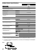
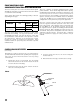
Radiant Heater Specifications Model I17 SPECIFICATIONS Maximum Input (Btuh) 17,100 200 CFM Ventilation Air to Support Combustion Zone Control Full Output Pressure PROPANE GAS OR NATURAL GAS 5 PSIG Zone Control, Low Fire Pressure PROPANE GAS OR NATURAL GAS 10 - 12 in. W.C. Heater Dimensions (See Fig. 1) “A” 16-7/8 in. “B” 10- 1/2 in. “C” 6 -1/2 in. Net Weight 5 lbs.12 oz. Fuel Consumption Per Hour Animal Coverage Per Heater (1) PROPANE GAS .80 lbs./hr. NATURAL GAS 17.
Safety Precautions WARNING Asphyxiation Hazard ■ Do not use this radiant heater for heating human living L.B. White Company to determine combustion air quarters. ventilation requirements of the heater. ■ Do not use in unventilated areas. ■ The flow of combustion and ventilation air must not be obstructed. ■ Lack of proper ventilation air will lead to improper combustion. ■ Proper ventilation air must be provided to support the combustion air requirements of the heater being used.
Safety Precautions 1. Do not attempt to install, repair or service this heater or the gas supply line unless you have continuing expert training and knowledge of gas heaters. Qualifications for service and installation of this equipment are as follows: QUALIFICATIONS FOR SERVICING AND INSTALLATION: a.
14. A qualified service person shall inspect the heater and its gas train at least on an annual basis. This should consist of, but is not limited to, the following points of action: -- Thorough inspection of the heater’s component parts for corrosion, stripped threads, etc. with subsequent parts replacement as necessary. -- Gas pressure checks. -- Start-up and shut down of the heaters and zone control panel to test for proper operation. 15. Turn off the gas supply when the heater is not in use.
involved for cleanliness in the thread areas and proper application of pipe compound before further tightening. 12. The heater is designed for either L.P. vapor withdrawal or natural gas, depending on model number. Do not use this heater in an LPG liquid withdrawal system. Do not permit LPG in liquid form to enter the heater at any time. -- Tighten the gas connection as necessary to stop the leak. 13.
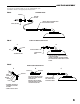
GAS TRAIN ASSEMBLY Your heater is supplied with one of the following gas train assemblies. Refer to the appropriate illustrations. FIG. 3 STANDARD HOSE BUSHING RIGID END OF HOSE TO GAS SUPPLY CONNECT HOSE TO CONTROL VALVE INLET, TIGHTEN SECURELY VALVE, SHUT-OFF 1/8 NPT FITTING KIT, PART #23406 FIG. 4 A B STEM FITTING ASSEMBLY NUT CONTROL VALVE INLET - ASSEMBLE FITTING - ATTACH FITTING TO CONTROL VALVE INLET & TIGHTEN SECURELY.
ZONE CONTROL PANEL COMPONENT FUNCTION AND INSTALLATION The zone control panel is a remote mounted control system allowing the operation of a specific amount of heaters within a certain zone of the building. These panels will control the following quantity of heaters depending on fuel type. Modulating System Model and Heat Output Fuel I17 L. P.
Start-Up Instructions 3. Fully depress the button on the safety control valve while applying flame to the inner cone point. Remove the vinyl cap from the safety valve if necessary. See Fig.8. Keep the button fully depressed for about 30 seconds until the inner cone stays lit. Release the button. Allow outer combustion cone to heat up completely. Replace the cap onto the safety control valve. WARNING Fire or Explosion Hazard ■ Do not force the safety control valve button.
Cleaning Instructions CAUTION ■ Disinfectants utilized in agricultural animal 6. Return the heater to its normal hanging position and relight the heater. FIG. 9 confinement buildings may contain chemicals damaging to components of the heater. ■ Protect the safety gas control valve and pressure valve by wrapping these components with a plastic bag before disinfecting. ■ Always make sure to remove the plastic bag or other protective covering before start up.
FIG. 11 B. FILTER (accessory) A. During continued use: WATER HOSE - Remove filter and shake off dust. - Do not squeeze or tap filter while filter is installed on heater. Doing so will cause dust to be blown into venturi tube or combustion cones. B. After continued use or before building repopulation: 3. Repeat steps 2 and 3 until water runs clean. - Remove filter and shake off dust. - Use compressed air or water (standard faucet pressure) to clean it.
Maintenance Instructions 1. Have your gas supplier check all gas piping annually for leaks or restrictions in gas lines. Also, at this time have your gas supplier clean out the sediment trap on the zone control panel of any debris that may have accumulated. 2. The heater’s surrounding area shall be kept clear and free from combustible materials, gasoline, and other flammable vapors and liquids. 3. Regulators can wear out and function improperly.
SAFETY GAS CONTROL VALVE 1. Disconnect the gas hose. 2. Disconnect the thermocouple from the safety valve. FIG. 12 SAFETY CONTROL VALVE 3. Loosen the jam nut on the air housing. JAM NUT O-RING 4. Turning counterclockwise, remove the safety control. AIR HOUSING When reassembling: -- Ensure o-ring is seated in jam nut. -- Apply Loctite (supplied with replacement) to first four threads of air housing.
THERMOSTATIC HEAD and MODULATING VALVE Individual Control Heaters and Modulating Zone Panels ■ The following service instructions apply to individual control or zone control heaters. ■ The head assembly includes the adjustable thermostatic head, capillary and sensor. The part numbers for the thermostatic heads are: -- Zone panel head: Part No. - 09416 w/ 26 ft. capillary -- Individual control head: Part No. - 09415 w/ 6 ½ ft.
BURNER COMBUSTION CONES and GASKET Very little servicing is required for the combustion cones and gasket. Routine cleaning is sufficient to ensure that the cones remain unblocked by dust and dirt. Periodic tightening of the the three burner plate nuts, (see Fig.18) ensures that the heater operates to normal combustion characterisitics. 4. Inspect the inner cone. See Fig.21. If the cone is in good condition, (cone weld seam not split or tip is not missing) then clean using the compressed air method.
THERMOCOUPLE 1. Loosen the thermocouple connector nut at the safety control valve. See Fig. 23. FIG. 24 2. Loosen the screw securing the clip holding the thermocouple’s auto reset temperature switch to the air housing. See Fig. 23. UPPER RETAINING NUT 3. Loosen upper retaining nut on thermocouple. See Fig. 24. KEY HOLE SLOT 4. Remove the thermocouple, with nuts and cover, from the heater. THERMOCOUPLE INSTALLED 5.
GAS PRESSURE CHECKS A. Preparation C.Reading Pressures 1. Obtain a pressure gauge test kit part no. 20736. 1. With the heater operating at full heat output and at minimum heat, the pressure gauge should read the pressure specified on the dataplate of the zone panel. 2. Close the fuel supply valve to the heater. 3. Brush or blow off any dust and dirt on or in the vicinity of the gas control valve. 4. Disconnect the gas hose from the heater. 2.
Troubleshooting Guide READ THIS ENTIRE SECTION BEFORE BEGINNING TO TROUBLESHOOT PROBLEMS. The following troubleshooting flow charts provide systematic procedures for isolating heater problems. The charts are intended for use by a QUALIFIED GAS HEATER SERVICE PERSON. DO NOT SERVICE THE HEATER UNLESS YOU HAVE BEEN PROPERLY TRAINED. WARNING Burn Hazard ■ Troubleshooting this system may require operating the heater with the burner on. Use extreme caution when working on the heater.
Provide 5 PSIG gas pressure. No Is proper gas pressure supplied to the zone panel or heater? Open all fuel supply valves. No Are all fuel supply valves to heater Yes open? Flame burning beyond outer cone, or lazy flame Problem 2 Heater does not light Problem 1 Yes Yes Clean the heaqter and filter. No Yes Tighten the burner nuts. Turn thermostat up to Its maximum setpoint.
Heater lights, but will not stay lit Problem 3 Yes Yes Check gas pressure to the heater Inlet with a gas gauge. Proper pressure at high heat should be 5 PSIG. Low heat is 10 in. W.C. No Yes Yes Is safety control valve defective? No Is thermocouple auto reset switch open.? Remove the component and clean It. Yes Yes Ensure the heater has been properly cleaned. Refer to Cleaning Instructions within this manual. If the heater has been cleaned, test the thermocouple for continuity.
Outer combustion cone does not heat up on high thermostat setting. Problem 4 Check for proper gas pressure to the heater. Proper pressure at high heat should read 5 PSIG. No Is proper gas pressure being supplied to the heater? No Are there blockages in gas hose, piping, air housing or venturi tube? Yes No Is secondary orifice plugged? Remove the component and clean it. Yes Remove orifice and clean it. B Replace thermostatic head valve body. -- OR -- A.
Yes No No Is the burner plate or burner gasket cracked? No Are burner assembly nuts loose? No Are air housing. venturi tube, burner orifice,filter, or inner cone partially plugged with dirt? No Is inner cone seam fractured or is tip damaged or missing? Does main burner decrease in heat when thermostatic head is set below room temperature? Check for proper gas pressure. Proper pressure at high heat should read 5 PSIG.
Heater Component Function Air Housing Secures safety control valve to venturi tube. Also allows combustion air to be drawn in to injector tube with gas flow for combustion. Safety Control Valve Safety shut off device used to feed fuel gas to the heater combustion cones for heating. Will shut off flow of gas completely if gas flame is extinguished. Burner Orifices Metering devices used to feed gas to combustion cones at a specific flow rate.
Parts Identification PARTS SCHEMATIC 21 26
PARTS LIST Item 1 2 3 4 4A 4B 4C 5 6 7 7A 7B 8 Description Venturi tube and burner assembly Cover plate with nuts Thermocouple with auto reset temperature switch Kit, combustion cones and gasket Gasket Inner cone Outer cone Burner plate Hardware for burner plate (nuts, screws, spacers, 3 each) Filter kit Filter Filter sleeve Safety control valve with cap 9 10 11 12 Cap for safety control Jam nut, for safety control Clip, thermocouple with screw Air housing with register plate, burner orifice, and jam nut
Warranty Policy EQUIPMENT L.B. White Co., Inc. warrants that the component parts of its equipment are free from defects in material and workmanship, when properly installed, operated, and maintained in accordance with the Installation and Maintenance Instructions, safety guides and labels contained with each unit. If, within 12 months from the date of purchase by the end user, any component is found to be defective, L.B. White Co., Inc.