Owner’s Manual and Instructions Modulating Infraconic Agricultural Building Radiant Heaters MODEL OUTPUT (Btuh) FUEL I3 2,800 Propane Vapor Withdrawal or Natural Gas Congratulations! You have purchased the finest radiant heater available for the heating of livestock in agricultural animal confinement buildings. Your new L.B. White radiant heater incorporates the benefits from the most experienced manufacturer of heating products using state-of-the-art technology. We, at L.B.
GENERAL HAZARD WARNING ■ Failure to comply with the precautions and instructions provided with this heater, can result in: — Death — Serious bodily injury or burns — Property damage or loss from fire or explosion — Asphyxiation due to lack of adequate air supply or carbon monoxide poisoning — Electrical shock ■ Read this Owner’s Manual before installing or using this heater. ■ Only properly-trained service people should repair or install this heater. ■ Save this Owner’s Manual for future use and reference.
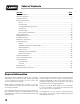
Table of Contents PAGE SECTION General Information . . . . . . . . . . . . . . . . . . . . . . . . . . . . . . . . . . . . . . . . . . . . . . . . . . . . . . . . . . . . . . . . . . .3 Heater Specifications . . . . . . . . . . . . . . . . . . . . . . . . . . . . . . . . . . . . . . . . . . . . . . . . . . . . . . . . . . . . . . . . . .4 Safety Precautions . . . . . . . . . . . . . . . . . . . . . . . . . . . . . . . . . . . . . . . . . . . . . . . . . . . . . . . . . . . . . . . . . . . .
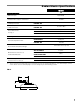
Radiant Heater Specifications Model I3 SPECIFICATIONS Maximum Input 2,800 BTUH 35 CFM Ventilation Air to Support Combustion Zone Control Full Output Pressure PROPANE GAS OR NATURAL GAS 5 PSIG Zone Control, Low Heat Pressure PROPANE GAS OR NATURAL GAS 10 - 12 in. W.C. Heater Dimensions See Fig. 1 “A” 7-5/8 in. “B” 7 in. “C” 3-1/2 in. Net Weight 3-1/2 lbs. PROPANE GAS .13 lbs./hr. NATURAL GAS 2.8 CFH Fuel Consumption Per Hour 24 in.
Safety Precautions WARNING Asphyxiation Hazard ■ Do not use this radiant heater for heating human living combustion air ventilation requirements of the heater. quarters. ■ Lack of proper ventilation air will lead to improper ■ Do not use in unventilated areas. combustion. ■ The flow of combustion and ventilation air must not be obstructed. ■ Proper ventilation air must be provided to support the combustion air requirements of the heater being used.
Safety Precautions 1. Do not attempt to install, repair or service this heater or the gas supply line unless you have continuing expert training and knowledge of gas heaters. Qualifications for service and installation of this equipment are as follows: QUALIFICATIONS FOR SERVICING AND INSTALLATION: a.
12. Inspect all heaters af ter room turn, or before repopulation. Such inspection should consist of, but is not limited to, the following points of action: -- Thorough cleaning of the exterior of the heater, its inlet venturi, combustion cones and filter. -- Thorough inspection of the heater’s component parts for corrosion, stripped threads, etc. with subsequent parts replacement as necessary. -- Insure proper clearance to combustible materials. -- Check for general cleanliness. Clean if necessary.
-- If necessary, replace the parts or components involved if the leak cannot be stopped. 11. Check all connections for gas leaks using approved gas leak detectors. Gas leak testing is performed as follows: -- Ensure all gas leaks have been identified and repaired before proceeding. WARNING ■ ■ ■ ■ Fire and Explosion Hazard Do not use open flame (matches, torches, candles, etc.) in checking for gas leaks. Use only approved leak detectors. Failure to follow this warning can lead to fires or explosions.
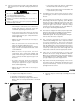
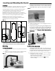
Locating and Mounting the Heater c. Locating The heater is designed to provide radiant heat to the entire creep mat or creep area on both sides of the crate divider. Using the drill template from the safety chain kit (included) position its holes at the locations previously marked. Drill 1/8 in. pilot holes at both sides. See Fig.5. FIG. 5 To properly utilize the heater, the producer must determine: a. Desired position of the heat zone relative to the sow b. Location of the creep mat relative to the sow.
c. FIG. 7 Using the lower base holes as templates, drill 5/16 in. holes through the divider panel , both sides. See Fig.8. Secure the base mount to the panel with nuts and bolts included. Proceed to Safety Chain Installation Instructions. FIG. 8 b.. Locate the heater with mount to the planned position on the crate panel. Push the assembly firmly onto the panel. LOWER HOLES INSTALL NUTS AND BOLTS BOTH ENDS Safety(part Chain 26771) The safety chain hanging kit must be installed.
HEATER CONTROL and OPERATION Proper temperature management is needed when using the I-3 radiant heater. The creep area, which is the comfort zone for piglets, is managed independently from the room temperature. The room’s temperature will be lower than the temperature needed for the creep area. Lower room temperatures create two benefits: -- Less fuel/energy consumption -- Increased sow feed intake which creates higher weaned weights.
Lighting Instructions FIG. 13 WARNING Fire or Explosion Hazard THERMOSTATIC HEAD ■ Do not force the safety gas control valve button. ■ Use only your hand to depress the gas control button. Never use any tools. ■ If the button will not depress by normal hand 100ºF 38ºC pressure, the control should be replaced by a qualified service person. ■ Force or attempted repair may result in fire or INDICATOR explosion, causing property damage, severe injury, or death.
Cleaning Instructions BETWEEN TURNS CAUTION ■ Disinfectants used in agricultural animal confinement buildings may contain chemicals damaging to components of the heater. This heater is used in the farrowing environment where the animals are turned approximately every 21 days and the rooms are typically pressure washed between turns. See the following for cleaning the heater bewtween turns. For longer term cleaning requirements, see the Maintenance Section of this manual.
Maintenance Instructions 1. Have your gas supplier check all gas piping annually for leaks or restrictions in gas lines. Also, at this time have your gas supplier clean out the sediment trap on the zone control panel of any debris that may have accumulated. 2. Regulators can wear out and function improperly. Have your gas supplier check the date codes on all regulators installed and check delivery pressures to the appliance to make sure that the regulator is suitable for continued use. FIG.
Service Instructions GENERAL WARNING Burn Hazard ■ Heater surfaces are extrememly hot for a period of time after the heater has been shut down. ■ Allow the heater to cool before performing service, maintenance, or cleaning. ■ Failure to follow this warning will result in burns causing injury. WARNING Fire and Explosion Hazard ■ Do not disassemble or attempt to repair any heater components or gas train components. 1.
THERMOCOUPLE 1. Remove the thermocouple bracket nut. See Fig. 18. FIG. 18 INJECTOR TUBE 2. Pull the thermocouple from its mounting location. NUT 3. Disconnect thermocouple from pilot safety gas control valve. Replacement thermocouple will include a factory installed locator bracket with retaining nut. THERMOCOUPLE LOCATION BRACKET THERMOCOUPLE HOLE STUD COMBUSTION CONES and GASKET 1 Remove all nuts from the three burner screws. See Fig.19. 2. Remove thermocouple from burner. 3.
GAS PRESSURE CHECKS A. Preparation C. Reading Pressures 1. Obtain an L.B. White pressure gauge test kit Part No. 20736. 1. With all of the heaters within the zone operating at full heat output and at minimum heat, the pressure gauge should read the pressure specified on the dataplate of the zone panel. 2. Close the fuel supply valve to the heater. 3. Brush or blow off any dust and dirt on or in the vicinity of the safety control valve. 4. Disconnect the gas hose from the heater. B. Gauge Installation 1.
Troubleshooting Guide READ THIS ENTIRE SECTION BEFORE BEGINNING TO TROUBLESHOOT PROBLEMS. The following troubleshooting flow charts provide systematic procedures for isolating heater problems. The charts are intended for use by a QUALIFIED GAS HEATER SERVICE PERSON. DO NOT SERVICE THE HEATER UNLESS YOU HAVE BEEN PROPERLY TRAINED. WARNING Burn Hazard ■ Troubleshooting this system may require operating the heater with the burner on. Use extreme caution when working on the heater.
19 Outer combustion cone does not heat up on high thermostat setting. Problem 2 No Has proper gas pressure been checked to the heater? Open all fuel supply valves. No Are all Fuel Supply Valves to Heater Open? Yes No Is orifice plugged? No Are there blockages in gas hose, piping, or venturi tube? Provide 5 PSIG gas pressure. No Is proper gas pressure supplied to the zone panel or heater? Yes Replace it. Yes Yes Remove the component and clean It.
20 Problem 3 No Is proper gas Yes pressure supplied to the heater? No Is button on safety control valveYes fully depressed? Yes Yes Yes No Is thermocouple contact nut tightened securely into gas control valve? Yes Snug contact nut in place. (Do not overtighten.) Check for debris between contact of thermocouple and electromagnet of valve. Remove the component and clean It. Replace orifice. Allow 30 - 60 seconds before releasing pilot button.
21 No Is proper gas pressure being supplied to the heater? Yes Yes No No Is inner cone weld seam aligned to burner plate notch? No Is the burner plate or burner gasket cracked? No Are burner assembly nuts loose? No Replace the orifice. Clean all other components. Position the inner cone weld seam in burner plate notch. Replace the burner plate.or gasket Tighten the nuts Yes Combustion Cone Kits Part Number 572129 Replace Combustion Cone. Remove thermostatic head from valve body: A.
Heater Component Function Burner Orifice Metering device used to feed gas to combustion cones at a specific flow rate. Shroud Reflective aluminum heat shield for heater. Double Combustion Chamber Made of special alloy steel. This is where combustion of gas occurs, providing radiant heat used in the warming process. Gas Hose Flexible connector used to convey gas from gas supply line to inlet of heater.
Parts Identification PARTS SCHEMATIC 23
PARTS LIST Item Description Part No.
Warranty Policy EQUIPMENT L.B. White Co., Inc. warrants that the component parts of its equipment are free from defects in material and workmanship, when properly installed, operated, and maintained in accordance with the Installation and Maintenance Instructions, safety guides and labels contained with each unit. If, within 12 months from the date of purchase by the end user, any component is found to be defective, L.B. White Co., Inc.