Owner’s Manual and Instructions Modulating Infraconic Agricultural Building Radiant Heaters MODELS OUTPUT (Btuh) I34 34,200 FUEL Propane Vapor Withdrawal or Natural Gas Congratulations! You have purchased the finest radiant heater available for the heating of livestock in agricultural animal confinement buildings. Your new L.B. White radiant heater incorporates the benefits from the most experienced manufacturer of heating products using state-of-the-art technology. We, at L.B.
GENERAL HAZARD WARNING ■ Failure to comply with the precautions and instructions provided with this heater, can result in: — Death — Serious bodily injury or burns — Property damage or loss from fire or explosion — Asphyxiation due to lack of adequate air supply or carbon monoxide poisoning — Electrical shock ■ Read this Owner’s Manual before installing or using this heater. ■ Only properly-trained service people should repair or install this heater.
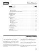
Table of Contents PAGE SECTION General Information . . . . . . . . . . . . . . . . . . . . . . . . . . . . . . . . . . . . . . . . . . . . . . . . . . . . . . . . . . . . . . . . . . .3 Heater Specifications . . . . . . . . . . . . . . . . . . . . . . . . . . . . . . . . . . . . . . . . . . . . . . . . . . . . . . . . . . . . . . . . . .4 Safety Precautions . . . . . . . . . . . . . . . . . . . . . . . . . . . . . . . . . . . . . . . . . . . . . . . . . . . . . . . . . . . . . . . . . . . .
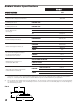
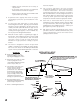
Radiant Heater Specifications Model I34 SPECIFICATIONS Maximum Input (Btuh) 34,200 Ventilation Air to Support Combustion Zone Control Full Output Pressure PROPANE GAS OR NATURAL GAS Zone Control, Low Output Pressure Heater Dimensions (See Fig. 1) Fuel Consumption Per Hour Recommended Height Installation For Livestock From Point of Combustion Cone to Floor 12 lbs.7 oz. PROPANE GAS 1.58 lbs./hr. CHICKENS 2500-3800 TURKEYS 34.2 CFH 800-950 SWINE 300 CHICKENS 6 - 7 ft. SWINE 4 - 5 ft.
WARNING Safety Precautions Asphyxiation Hazard ■ Do not use this radiant heater for heating human living L.B. White Company to determine combustion air quarters. ventilation requirements of the heater. ■ Do not use in unventilated areas. ■ The flow of combustion and ventilation air must not be obstructed. ■ Proper ventilation air must be provided to support the combustion air requirements of the heater being used.
Safety Precautions 1. Do not attempt to install, repair or service this heater or the gas supply line unless you have continuing expert training and knowledge of gas heaters. Qualifications for service and installation of this equipment are as follows: QUALIFICATIONS FOR SERVICING AND INSTALLATION: a.
13. The grower shall inspect the heater before building repopulation. Such inspection should consist of, but is not limited to, the following points of action: control panel to test for proper operation. -- Leak check of all pipe joints and hose connections. -- Insure proper clearance of heater to nearest combustible materials. -- Thorough cleaning of the exterior of the heater, its inlet venturi, combustion cones and filter (if applicable). -- Check for general cleanliness. Clean if necessary.
heater at any time. -- Tighten the gas connection as necessary to stop the leak. -- If necessary, replace the parts or components involved if the leak cannot be stopped. 13. The corrosive atmosphere present in animal confinement buildings can cause component failure or heater malfunction. The heater should be periodically inspected and cleaned in accordance with the Maintenance and Cleaning Instructions in this manual.
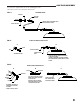
GAS TRAIN ASSEMBLY Your heater is supplied with one of the following gas train assemblies. Refer to the appropriate illustrations. FIG. 3 STANDARD HOSE BUSHING RIGID END OF HOSE TO GAS SUPPLY CONNECT HOSE TO CONTROL VALVE INLET, TIGHTEN SECURELY VALVE, SHUT-OFF FIG. 4 1/8 NPT FITTING KIT, PART #23406 A B STEM FITTING ASSEMBLY NUT CONTROL VALVE INLET - ASSEMBLE FITTING - ATTACH FITTING TO CONTROL VALVE INLET & TIGHTEN SECURELY.
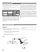
ZONE CONTROL PANEL COMPONENT FUNCTION AND INSTALLATION The zone control panel is a remote mounted control system allowing the operation of a specific amount of heaters within a certain zone of the building. These panels will control the following quantity of heaters depending on fuel type. Model and Heat Output I34 (34,200 BTUH) Modulating System Fuel L. P.
WARNING Fire or Explosion Hazard Start-Up Instructions FIG. 7 THERMOSTATIC HEAD ■ Do not force the safety gas control valve button. ■ Use only your hand to depress the gas control button. Never use any tools. ■ If the button will not depress by normal hand pressure, the control should be replaced by a qualified service person. ■ Force or attempted repair may result in fire or explosion, causing property damage, severe injury, or death.
Cleaning Instructions CAUTION ■ Disinfectants utilized in agricultural animal confinement buildings may contain chemicals damaging to components of the heater. ■ Protect the safety gas control valve and pressure valve by wrapping these components with a plastic bag before disinfecting. 5. Inspect the cones and venturi tube to make sure these areas are clean. 6. Return the heater to its normal hanging position and relight the heater. FIG.
FIG. 11 WATER HOSE 8. Relight the heater to dry out the cones and the venturi tube. B. FILTER A. During continued use: - Remove filter and shake off dust. - Do not squeeze or tap filter while filter is installed on heater. Doing so will cause dust to be blown into venturi tube or combustion cones. B. After continued use or before building repopulation: 4. Repeat steps 2 and 3 until water runs clean. 5. Remove the plastic bag. Inspect the cones and venturi tube to make sure these areas are clean. 6.
Maintenance Instructions 1. Have your gas supplier check all gas piping annually for leaks or restrictions in gas lines. Also, at this time have your gas supplier clean out the sediment trap on the zone control panel of any debris that may have accumulated. 6. If any warning or instruction labels, dataplates, etc. become lost or hard to read, replace them immediately. Do not operate the heater until you have all instructions and can read and understand them. 3.
1. Disconnect the gas hose. 2. Loosen the gas supply tube compression nut and swing the tube away from the safety control valve. FIG. 12 SAFETY GAS CONTROL VALVE PILOT SAFETY VALVE SAFETY CONTROL VALVE BYPASS GAS TUBE SUPPLY TUBE GAS SUPPLY 3. Remove the thermocouple from the safety control valve. SCREW 4. Loosen the screw on the injector body. 5. Remove the safety gas control valve with injector tube from the heater. 6. Remove the injector tube.
THERMOSTATIC HEAD Individual Control Heaters and Modulating Zone Panels ■ The following service instructions are the same on individual control or zone control heaters. ■ The head assembly includes the adjustable thermostatic head, capillary and sensor. The part numbers for the thermostatic heads are: -- Zone panel head: Part No. - 09416 w/ 26 ft. capillary -- Individual control head: Part No. - 09415 w/ 6 ½ ft.
MAIN BURNER PRESSURE VALVE A. Removal 1. Loosen gas supply tube compression nuts and remove gas tube. See Fig. 18. 2. Remove pressure valve from injector body by firmly grasping the pressure switch and turning it counter clockwise. ■ The replacement pressure valve will ship with a small tube of Loctite thread lock. ■ Apply Loctite sparingly (normally 2 drops is sufficient) to the upper threads of the adapter. See Fig. 19. ■ Thread the pressure valve into the injector body.
THERMOCOUPLE 1. Remove the thermocouple at the pilot gas control valve. See Fig. 20. FIG. 21 2. Loosen the thermalfuse retaining clip screw. See Fig. 20. 3. Loosen upper retaining nut on thermocouple. See Fig. 21. 4. Remove the thermocouple, with nuts and cover, from the heater assembly. 5. Transfer nuts and cover to replacement thermocouple. Position as shown in Fig. 22. 6. Position the thermalfuse under the retaining clip and tighten the screw. 7.
GAS PRESSURE CHECKS A. Preparation C. Reading Pressures 1. Obtain an L.B. White pressure gauge test kit Part No. 20736. 2. Close the fuel supply valve to the heater. 3. Brush or blow off any dust and dirt on or in the vicinity of the gas control valve. 4. Disconnect the gas hose from the heater. B. Gauge Installation 1. Connect the pressure test kit between the heaer and its gas supply hose as shown in Fig. 24.
Troubleshooting Guide READ THIS ENTIRE SECTION BEFORE BEGINNING TO TROUBLESHOOT PROBLEMS. The following troubleshooting flow charts provide systematic procedures for isolating heater problems. The charts are intended for use by a QUALIFIED GAS HEATER SERVICE PERSON. DO NOT SERVICE THE HEATER UNLESS YOU HAVE BEEN PROPERLY TRAINED. TEST EQUIPMENT REQUIRED The following pieces of test equipment will be required to troubleshoot this system with minimal time and effort.
Inner Combustion Cone Will Not Light Problem 1 Open All Fuel Supply Valves. No Are all Fuel Supply Valves to Heater Open? Yes Provide 5 PSIG Gas Pressure. No Is Proper Gas Pressure Supplied to the Zone Panel or Heater? Yes Turn Thermostat Up to Its Maximum Setpoint. No Is Thermostatic Head Set to Maximum? Yes Defective Safety Control Valve. Replace the Safety Control Valve.
No Is Button on Safety Control Valve Fully Depressed? Yes Yes Yes Check Gas Pressure to the Heater Inlet with a Gas Gauge. Proper Pressure at High Heat Should Read 5 PSIG. Low Heat is 10 in. W.C. No Is Proper Gas Pressure Supplied to Yes the Heater? No Is the Gas Hose Partially Plugged? No No Did you Allow Sufficient Time for the Thermocouple to Warm Up? Yes Is Safety Control Valve Defective? No Is Thermocouple Weak or Defective? Remove the Component and Clean It. Yes Yes A.
Outer Combustion Cone Does Not Heat Up on High Thermostat Setting. Problem 3 Check for Proper Gas Pressure to the Heater. Proper Pressure at High Heat Should Read 5 PSIG. No Is Proper Gas Pressure Being Supplied to the Heater? No Are There Blockages in Gas Hose, Piping, Tubing Assembly, Injector Body or Venturi Tube? No Is Secondary Orifice Plugged? Remove the Component and Clean It. Yes Remove Orifice and Clean It. C. Replace Thermostatic Head Valve Body. -- OR -- B.
Heater Backflashes Gas Through Air Inlet. Problem 4 No Is Proper Gas Pressure Being Supplied to the Heater? Yes No Is Inner Cone Weld Seam Aligned to Burner Plate Notch? No Is the Burner Plate or Burner Gasket Cracked? No Are Burner Assembly Nuts Loose? No No Clean these Components. Position the Inner Cone Weld Seam in Burner Plate Notch. Replace the Burner Plate.or Gasket Tighten the Nuts Yes Combustion Cone Kits Part Number 21088 Replace Combustion Cone.
Burner Orifices Metering devices used to feed gas to combustion cones at a specific flow rate. Canopy Reflective aluminum heat shield for heater. Double Combustion Chamber Made of special alloy steel. This is where combustion of gas occurs, providing radiant heat used in the warming process. Gas Hose Flexible connector used to convey gas from gas supply line to inlet of heater. Injector Body Secures pilot gas valve to injector tube.
Parts Identification PARTS SCHEMATIC 7 9 24 15 11 16 6 5 25 18 34 4 32 33 34A 34B 3 2 1 2 29A 36 29B INDIVIDUAL CONTROL 27 35 28 37 31 29C 26 26
Item 1 2 3 4 5 6 7 9 11 15 16 18 24 25 26 27 28 29 29A 29B 29C 31 32 33 34 34A 34B 35 36 37 Description Venturi Tube and Burner Assembly Thermocouple Retaining Nut Thermocouple with Fusible Link Injector Casting with Air Register Plate Retaining Screw for Injector Tube Primary Burner Orifice (Low Heat) Injector Tube Pressure Valve Safety Control Valve Retaining Screw for Control Assembly and Thermocouple Thermocouple Fuse Clip Keyring Tubing, Pilot Safety Valve to Pressure Valve Secondary Orifice (H
Warranty Policy EQUIPMENT L.B. White Co., Inc. warrants that the component parts of its equipment are free from defects in material and workmanship, when properly installed, operated, and maintained in accordance with the Installation and Maintenance Instructions, safety guides and labels contained with each unit. If, within 12 mon ths fro m the date of purchase by the end user, any component is found to be defective, L.B. White Co., Inc. will at its option, repair PARTS L.B. White Co., Inc.