Owner’s Manual and Instructions Pilot Ignition Infraconic Agricultural Building Radiant Heaters MODELS I34* OUTPUT (Btuh) FUEL 34,200 Propane Vapor Withdrawal or Natural Gas Certification by: * Models with InstaClear™ Pilot Clean Out are not CSA approved. Congratulations! You have purchased the finest radiant heater available for the heating of livestock in agricultural animal confinement buildings. Your new L.B.
GENERAL HAZARD WARNING ■ Failure to comply with the precautions and instructions provided with this heater, can result in: — Death — Serious bodily injury or burns — Property damage or loss from fire or explosion — Asphyxiation due to lack of adequate air supply or carbon monoxide poisoning — Electrical shock ■ Read this Owner’s Manual before installing or using this heater. ■ Only properly-trained service people should repair or install this heater. ■ Save this Owner’s Manual for future use and reference.
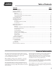
Table of Contents PAGE SECTION General Information . . . . . . . . . . . . . . . . . . . . . . . . . . . . . . . . . . . . . . . . . . . . . . . . . . . . . . . . . . . . . . . . . . .3 Heater Specifications . . . . . . . . . . . . . . . . . . . . . . . . . . . . . . . . . . . . . . . . . . . . . . . . . . . . . . . . . . . . . . . . . .4 Safety Precautions . . . . . . . . . . . . . . . . . . . . . . . . . . . . . . . . . . . . . . . . . . . . . . . . . . . . . . . . . . . . . . . . . . . .
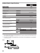
Radiant Heater Specifications Model I34 SPECIFICATIONS Maximum Input (Btuh) 34,200 Ventilation Air to Support Combustion Zone Control Full Output Pressure Zone Control, Pilot System Pilot Pressure 400 CFM PROPANE VAPOR OR NATURAL GAS PROPANE VAPOR OR NATURAL GAS “A” “B” “C” Heater Dimensions (See Fig.
Safety Precautions WARNING Asphyxiation Hazard ■ Do not use this radiant heater for heating human living L.B. White Company to determine combustion air quarters. ventilation requirements of the heater. ■ Do not use in unventilated areas. ■ The flow of combustion and ventilation air must not be obstructed. ■ Lack of proper ventilation air will lead to improper combustion. ■ Proper ventilation air must be provided to support the combustion air requirements of the heater being used.
Safety Precautions 1. Do not attempt to install, repair or service this heater or the gas supply line unless you have continuing expert training and knowledge of gas heaters. Qualifications for service and installation of this equipment are as follows: QUALIFICATIONS FOR SERVICING AND INSTALLATION: a.
repopulation. Such inspection should consist of, but is not limited to, the following points of action: control panel to test for proper operation. -- Leak check of all pipe joints and hose connections. -- Insure proper clearance of heater to nearest combustible materials. -- Thorough cleaning of the exterior of the heater, its air inlets, combustion cones and filter (if applicable). -- Check for general cleanliness. Clean if necessary. -- Check for tightness of the gas hose connections.
joints as well as the gas control valve inlet and outlet connections with approved gas leak detectors. -- If a leak is detected, check the components involved for cleanliness in the thread areas and proper application of pipe compound before further tightening. -- Tighten the gas connection as necessary to stop the leak. -- If necessary, replace the parts or components involved if the leak cannot be stopped. -- Ensure all gas leaks have been identified and repaired before proceeding. 9.
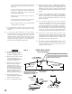
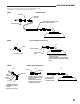
GAS TRAIN ASSEMBLY Your heater is supplied with one of the following gas train assemblies. Refer to the appropriate illustrations. FIG. 3 STANDARD HOSE BUSHING RIGID END OF HOSE TO GAS SUPPLY CONNECT HOSE TO CONTROL VALVE INLET, TIGHTEN SECURELY VALVE, SHUT-OFF 1/8 NPT FITTING KIT, PART #23406 FIG. 4 A B STEM FITTING ASSEMBLY NUT CONTROL VALVE INLET - ASSEMBLE FITTING - ATTACH FITTING TO CONTROL VALVE INLET & TIGHTEN SECURELY.
ZONE CONTROL PANEL FUNCTION AND INSTALLATION The zone control panel is a remote mounted control system allowing the operation of a specific amount of heaters within a certain zone of the building. These panels will control the following quantity of heaters depending on fuel type. Solenoid Zone Control System Fuel Medium Capacity Panel High Capacity Panel I34 L. P.
Start-Up Instructions WARNING 3. Fully depress the pilot button on the pilot safety control valve while applying flame to the main burner cone point. On initial start-up leave the main burner on for several minutes to bleed residual air from the system. 4. De-energize the solenoid of the zone control panel. The pilot flame should light and remain lit upon completion of transition from full output to pilot. Fire or Explosion Hazard ■ Do not force the gas control button.
Cleaning Instructions CAUTION ■ Disinfectants utilized in agricultural animal confinement buildings may contain chemicals damaging to components of the heater. ■ Protect the pilot gas control valve, pressure valve, and pilot relight valve by wrapping these components with a plastic bag before disinfecting. ■ Always make sure to remove the plastic bag or other protective covering before start up. 5. Repeat Steps 3 and 4 until the cones and the venturi tube are no longer emitting dust. 6.
B. Use the clean-out feature at the start of each new growing cycle, or when plugging of the orifice occurs. Indications of pilot orifice plugging are: FIG. 10 WATER HOSE -- Weak pilot flame center -- Pilot outages FIG. 11 PLUNGER PUSH BUTTON BUTTON TOPOF OF BODY TOP BODY 4. Repeat steps 2 and 3 until water runs clean. 5. Remove the plastic bag and inspect the cones and venturi tube to make sure these areas are clean. 6.
Maintenance Instructions 1. Have your gas supplier check all gas piping annually for leaks or restrictions in gas lines. Also, at this time have your gas supplier clean out the sediment trap on the zone control panel of any debris that may have accumulated. 6. If any warning or instruction labels, dataplates, etc. become lost or hard to read, replace them immediately. Do not operate the heater until you have all instructions and can read and understand them. 2.
PILOT ORIFICE, INSTACLEAR™ & STANDARD The instructions apply to both pilot designs. 5. Loosen orifice holder. 1. Loosen injector tube screw. 6. Remove pilot orifice from its holder. 2. Loosen pilot tube compression nut at gas inlet to pilot assembly. 7. Clean orifice. ■ Use care when servicing InstaClear™ orifice to avoid 3. Remove thermocouple from pilot safety control valve. damage to clean-out pin. 4. Slightly pull control assembly with pilot tube away from injector body. FIG.
PILOT SAFETY GAS CONTROL VALVE 1. Remove thermocouple from the pilot safety control valve. 2. Loosen the injector tube screw on the injector body and the compression nut at the outlet of the pilot relight valve. Pull control assembly from heater. FIG. 14 ADAPTER PILOT SAFETY CONTROL VALVE PILOT RE-LIGHT VALVE PRESSURE VALVE ADAPTER 3. Remove pressure valve from pilot control valve. 4. Remove the adapter connecting the pilot control valve to pilot relight valve.
PILOT RELIGHT VALVE 1. Remove thermocouple from pilot safety control valve. FIG. 17 PILOT SAFETY CONTROL VALVE 2. Loosen pilot tube compression nut at outlet of pilot re-light valve. PILOT RE-LIGHT VALVE ADAPTER 3. Loosen injector tube screw and pull control assembly from heater. 4. Remove pressure valve from pilot safety control valve. ADAPTER PRESSURE VALVE COMPRESSION NUT PRESSURE VALVE ADAPTER 5. Remove pilot safety control from adapter at pilot relight valve inlet. INJECTOR TUBE SCREW 6.
BURNER ORIFICE 1. Remove the thermocouple at the pilot control valve. 2. Loosen the injector body screw securing the thermocouple retaining clip. FIG. 18 3. Loosen compression nut at outlet of pilot relight regulator. 4. Loosen injector tube screw. 5. Pull injector body from heater. INJECTOR BODY SCREW INJECTOR TUBE SCREW PILOT RE-LIGHT REGULA VALVE COMPRESSION NUT 6. Using a 6 mm hex nut driver, remove orifice from the injector body by turning counter-clockwise. 7.
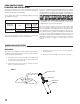
LEAD END OF THERMOCOUPLE FIG. 23 FIG. 22 THERMOFUSE COVER 5/16" FINISHED THERMOCOUPLE POSITION INJECTOR TUBE THERMOCOUPLE LEAD THERMOCOUPLE BODY COVER RETAINING NUT UPPER NUT COVER LOWER NUT 1/2 IN TO 9/16 IN THERMOCOUPLE TIP LOCATION HOLE IN PLATE THERMOCOUPLE INSTALLED GAS PRESSURE CHECKS A. Preparation 1. Obtain an L.B. White pressure gauge test kit - Part No. 20736. 2. Close the fuel supply valve to the heater. 3.
Troubleshooting Guide READ THIS ENTIRE SECTION BEFORE BEGINNING TO TROUBLESHOOT PROBLEMS. The following troubleshooting flow charts provide systematic procedures for isolating heater problems. The charts are intended for use by a QUALIFIED GAS HEATER SERVICE PERSON. DO NOT SERVICE THE HEATER UNLESS YOU HAVE BEEN PROPERLY TRAINED. TEST EQUIPMENT REQUIRED WARNING Burn Hazard ■ Troubleshooting this system may require operating the heater with the burner on. Use extreme caution when working on the heater.
Pilot Will Not Light Problem 1 Open All Fuel Supply Valves. No Are all Fuel Supply Valves to Heater Open? Yes Yes Provide 5 PSIG Gas Pressure to Zone Panel. Ensure 20 in. W.C. Pressure is Delivered to Heater with Only Pilot Operating. No Is Proper Gas Pressure Supplied to the Zone Panel or Heater? Turn Thermostat Up to Its Maximum Setpoint. No Is Thermostat Set Above Room Temperature? Yes Yes Yes Yes Yes Yes Defective Pilot Safety Control Valve. Replace the Pilot Safety Control Valve.
No Is the Gas Hose or Pilot Line Partially Plugged? No Are Pilot Screen or Pilot Orifice Plugged? Yes Yes Check Gas Pressure to the Heater Inlet with a Gas Gauge. Proper Pressure at High Fire - 5 PSIG. Pilot Pressure - 20 in. W.C. No Yes Is Pilot Safety Control Valve Defective? No Is Thermocouple Defective? Yes Remove the Components and Clean with Compressed Air. Yes A. Check Thermofuse in Thermocouple for Continuity. If Thermofuse is Open, Replace Thermocouple. B.
Outer Combustion Cone Does Not Heat Problem 4 Pilot Does Not Relight After Main Burner Shuts Down Problem 3 Check for Proper Gas Pressure to the Heater with a Gas Gauge. Proper Pressure at High Fire - 5 PSIG. Pilot Pressure - 20 in. W.C.
No Is Proper Gas Pressure Being Supplied to the Heater? Yes Is Inner Cone Weld Seam Aligned to Burner Plate Notch? No Is the Burner Plate or Burner Gasket Cracked? No Are Burner Assembly Nuts Loose? No Replace Thermostat. No Clean these Components. Replace the Burner Plate.or Gasket Tighten the Nuts Yes Combustion Cone KitS Part NumbeR 21088 Replace Combustion Cone. Yes Defective Solenoid Valve on Zone Panel, or Debris is Lodged in Plunger of Solenoid. Replace Solenoid Valve Assembly.
Heater Component Function Burner Orifices Metering devices used to feed gas to combustion cones at a specific flow rate. Canopy Reflective aluminum heat shield for heater. Double Combustion Chamber Made of special alloy steel. This is where combustion of gas occurs, providing radiant heat used in the warming process. Consists of a small inner cone and large outer cone. Gas Hose Flexible connector used to convey gas from gas supply line to inlet of heater.
Parts Identification PARTS SCHEMATIC 25 11 12 13 14 9 20 5 8 16 15 18 7 10 6 20A 22 31 24 22A 4 23 24A 22B 24B 3 2 2 34 1 30 29 28 27 26 26
PARTS LIST Item Description 1 2 3 4 Venturi Tube & Burner Assembly Thermocouple Retaining Nut Thermocouple w/ Fusible Link Injector Body w/ Register Plate 5 6 Screw, Injector Tube Burner Orifice Part Number Propane Gas Natural Gas Propane Gas Natural Gas 7 8 9 10 11 12 Injector Tube Adapter, Injector Tube to Pressure Switch Pressure Switch Nut Pilot Safety Control Valve Adapter, Pilot Control to Pilot Regulator 13 14 15 16 18 20 20A 22 Pilot Relight Valve Adapter, 1/4 NPT x 1/4 Compression Screw,
Warranty Policy EQUIPMENT L.B. White Co., Inc. warrants that the component parts of its equipment are free from defects in material and workmanship, when properly installed, operated, and maintained in accordance with the Installation and Maintenance Instructions, safety guides and labels contained with each unit. If, within 12 months from the date of purchase by the end user, any component is found to be defective, L.B. White Co., Inc.