Owner’s Manual and Instructions Spark Ignition Infraconic Agricultural Building Radiant Heaters MODELS I34 OUTPUT (Btuh) 34,200 FUEL Propane Vapor Withdrawal or Natural Gas Congratulations! You have purchased the finest radiant heater available for the heating of livestock in agricultural animal confinement buildings. Your new L.B. White radiant heater incorporates the benefits from the most experienced manufacturer of heating products using state-of-the-art technology. We, at L.B.
GENERAL HAZARD WARNING ■ Failure to comply with the precautions and instructions provided with this heater, can result in: — Death — Serious bodily injury or burns — Property damage or loss from fire or explosion — Asphyxiation due to lack of adequate air supply or carbon monoxide poisoning — Electrical shock ■ Read this Owner’s Manual before installing or using this heater. ■ Only properly-trained service people should repair or install this heater.
Table of Contents SECTION PAGE General Information . . . . . . . . . . . . . . . . . . . . . . . . . . . . . . . . . . . . . . . . . . . . . . . . . . . . . . . . . . . . . . . . . . .3 Heater Specifications . . . . . . . . . . . . . . . . . . . . . . . . . . . . . . . . . . . . . . . . . . . . . . . . . . . . . . . . . . . . . . . . . .4 Safety Precautions . . . . . . . . . . . . . . . . . . . . . . . . . . . . . . . . . . . . . . . . . . . . . . . . . . . . . . . . . . . . . . . . . . . .
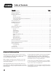
Radiant Heater Specifications Model I34 SPECIFICATIONS Maximum Input (Btuh) 34,200 Ventilation Air to Support Combustion 400 CFM Inlet Gas Supply Pressure at the Heater FULL OUTPUT MAX. ZONE CONTROLLED MAX. (On/Off Version) Fuel Consumption Per Hour Electrical Supply (Volts/HZ/Phase) Amp Draw “C” 10 3/8 in. “B” 15 lbs. 8 oz. 1.58 lbs./hr. NATURAL GAS 34.2 CFH 120/60/1 0.5 CHICKENS CHICKENS (2) 20 1/4 in.
Safety Precautions WARNING Asphyxiation Hazard ■ Do not use this radiant heater for heating human living L.B. White Company to determine combustion air quarters. ventilation requirements of the heater. ■ Do not use in unventilated areas. ■ The flow of combustion and ventilation air must not be obstructed. ■ Proper ventilation air must be provided to support the combustion air requirements of the heater being used.
1. Do not attempt to install, repair or service this heater or the gas supply line unless you have continuing expert training and knowledge of gas heaters. Qualifications for service and installation of this equipment are as follows: QUALIFICATIONS FOR SERVICING AND INSTALLATION: a.
-- Insure proper clearance of heater to nearest combustible materials. -- Leak check of all pipe joints and hose connections. -- Thorough cleaning of the exterior of the heater, its inlet venturi, combustion cones and filter (if applicable). -- Check for general cleanliness. Clean if necessary. -- Check for tightness of the gas hose connections. 14. A qualified service person shall inspect the heater and its gas train at least on an annual basis.
-- With the main burner in operation, check all connections, hose connections, fittings and joints as well as the gas control valve inlet and outlet connections with approved gas leak detectors. 13. Infraconic heaters require a regulated gas supply to the gas inlet. Exceeding the gas inlet pressure rating can result in poor per formance and unreliable operation. Refer to page 4 of this manual for information on gas pressures relating to specific models.
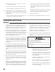
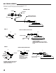
GAS TRAIN ASSEMBLY This heater is supplied with one of the following gas train assemblies. Refer to the appropriate illustrations. FIG. 3 STANDARD HOSE BUSHING RIGID END G OF HOSE TO GASG SUPPLY CONNECT HOSE TO GASG INLET, TIGHTEN SECURELY VALVE, SHUT-OFF FIG. 4 1/8 NPT FITTING KIT, PART #23406 A B STEM FITTING ASSEMBLY NUT CONTROL VALVEG INLET - ASSEMBLE FITTING - ATTACH FITTING TO GAS INLETG & TIGHTEN SECURELY.
ZONE CONTROL PANEL FUNCTION AND INSTALLATION With proper (5 PSIG) gas pressure supplied, spark ignition heaters will operate in the standard ON/OFF mode when electrically connected to a building environment controller or thermostat If you require two stages of heat for greater temperature control, a two stage solenoid operated zone panel must be installed.
Start-Up Instructions Follow steps 1-5 on initial start up after heater installation by a qualified gas heater service person. For normal startup, simply turn the building thermostat above room temperature. 1. 2. 3. 4. 5. Connect the heater to an approved electrical supply and building’s temperature control system. Open all gas supply valves to the heater and check for gas leaks at all connections using approved leak detectors.
Cleaning Instructions 5. Inspect the cones and venturi tube to make sure these areas are clean. It is important to clean the heater and the optional dust filter on a regular basis to maintain proper combustion and to eliminate future problems. Do not clean the heater with water or other liquids. The frequency of cleaning will var y depending upon livestock being raised and overall ventilation of the building. Problems associated with lack of cleaning typically are: 6.
Maintenance Instructions 1. Have your gas supplier check all gas piping annually for leaks or restrictions in gas lines. Also, at this time have your gas supplier clean out the sediment trap on the zone control panel of any debris that may have accumulated. 2. The heater’s surrounding area shall be kept clear and free from combustible materials, gasoline, and other flammable vapors and liquids. 3. Regulators can wear out and function improperly.
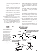
1. Disconnect the electrical leads from the ON/OFF switch. ON/OFF SWITCH FIG. 9 BOOT 2. Remove the rubber boot from the ON/OFF switch. See Fig. 9. Remove the switch from the control box. SWITCH ■ Handle the module at the edges of the board ■ Do not touch or allow any contact to the module IGNITION MODULE FIG. 10 IGNITION LEAD components, otherwise damage may occur. 1. Disconnect all electrical leads from the ignition control terminals. IGNITION CONTROLG MOUNTING SCREWS 2.
HIGH VOLTAGE IGNITION LEAD 1. Disconnect the igniter lead from ignition module. 2. Loosen the water tight connector nut. See Fig. 12. Pull the ignition lead through this connection. FIG. 12 C DISCONNECT FROM DISCONNECT IGNITOR LEAD LEAD FROM LOOSEN NUT LOOSEN WATER TIGHT NUT B IGNITOR TERMINAL 3. Disconnect the high voltage ignition lead from the A DISCONNECT DISCONNECT ignitor. See Fig. 12. IGNITORLEAD LEAD FROM FROM 4. Remove the connector nut from the ignition cable.
d. Position the tool between inner cone and ignitor tip. See Fig. 14c. FIG. 14c e. If the gap exceeds the minimum to maximum tolerances of the tool, reset the gap: -- loosen igniter mounting screws. -- reposition the igniter assembly until the gap is within the proper tolerances. f. Tighten the igniter mounting screws. INNER CONE TOOL .175 GAP BETWEEN ELECTRODE AND CONE ■ This heater is equipped with a manual reset high limit switch.
GAS CONTROL VALVE 1. Brush or blow off any dust in vicinity of gas control valve. 2. Disconnect the gas hose and remove control box cover. 3. Loosen water tight connector nut at the control box for the power supply leads of the control valve. 4. Disconnect the valve’s electrical leads from the ignition module. 5. Remove the connector nut from the valve leads. 6. Loosen the valve ground and attachment screw at the injector body. GAS PRESSURE CHECKS A. Preparation 1. Obtain an L.B.
READ THIS ENTIRE SECTION BEFORE BEGINNING TO TROUBLESHOOT PROBLEMS. The following troubleshooting flow charts provide systematic procedures for isolating heater problems. The charts are intended for use by a QUALIFIED GAS HEATER SERVICE PERSON. DO NOT SERVICE THE HEATER UNLESS YOU HAVE BEEN PROPERLY TRAINED. TEST EQUIPMENT REQUIRED The following pieces of test equipment will be required to troubleshoot this system with minimal time and effort. • Digital Multimeter - For measuring voltage.
No Are All Fuel Supply Valves Open? Yes Check for Voltage and Resistance of Switch and Electrical Leads Between Switches and Ignition Control. Replace if Defective. No Yes Yes Yes Yes A. Check Igniter for Defects, Cleanliness, and Proper Gap. B. Check Ignition Lead. Verify Resistance of Lead. Connections and No Cuts Replace if Necessary. C. If Igniter and Ignition Lead are Good, Replace Ignition Control.
Heater Backflashes Gas Through Air Inlet. Problem 3 Heater Lights but will not Stay Lit Problem 2 20 Yes No Is Proper Pressure Supplied Yes to the Heater? Check for Proper Gas Pressure. Proper Pressure at High Heat Should Read 5 PSIG. No Is Proper Gas Pressure Being Supplied to the Heater? Yes Yes Yes Yes Clean these Components. Replace the Burner Plate.or Gasket Tighten the Nuts Yes Combustion Cone Kits Part Number 21088 Replace Combustion Cone. Remove and Clean the Filter.
Electrical Connection and Ladder Diagram CAUTION: REFER TO THE HEATER'S ELECTRICAL CONNECTION DIAGRAM WHEN SERVICING TO AVOID WIRING ERRORS AND HEATER MALFUNCTION. CHECK FOR PROPER OPERATION AFTER SERVICING.
Burner Orifice Metering device used to feed gas to combustion cones at a specific flow rate. Canopy Reflective aluminum heat shield for heater. Double Combustion Chamber Made of special alloy steel. This is where combustion of gas occurs, providing radiant heat used in the warming process. Consists of small inner cone and large outer cone Gas Control Valve Component that houses electromagnet which is energized by voltage and therefore opens or closes to supply or shut off the flow of gas to the burner.
Parts Identification PARTS SCHEMATIC 9 10 23 32 11 27 30 35 25 37 4 24 34 26 8 28 6 31 31A 31B 20 29 2 1A 40 3 17 42 16 7 36 39 38 41 1B 21 14 18 13 33 19 23
Item 1A 1B 2 3 4 6 7 8 10 13 14 16 17 18 19 20 21 22 23 24 25 26 27 28 29 30 31 31A 31B 32 33 34 35 36 37 38 39 40 41 42 43 44 Description Inner Cone Outer Cone Combustion Cone Kit with Gasket Gasket Plate, Burner Igniter Kit Spacer Screw 10-32 x 1 1/2 Nut 10-32 Key Ring Lead, Igniter w/ Boot Connector, Liquid Tight Control, Direct Spark Ignition Switch, On/Off Boot, On/Off Switch Bracket, Control Box Control Box Cover w/ Gasket Control Box Bottom Bushing Adapter, Hose Valve, Gas Control w/ Electrical
Warranty Policy EQUIPMENT L.B. White Co., Inc. warrants that the component parts of its equipment are free from defects in material and workmanship, when properly installed, operated, and maintained in accordance with the Installation and Maintenance Instructions, safety guides and labels contained with each unit. If, within 12 mon ths fro m the date of purchase by the end user, any component is found to be defective, L.B. White Co., Inc.