Owner’s Manual and Instructions Modulating Infraconic Agricultural Building Radiant Heaters MODELS OUTPUT (Btuh) FUEL I5 5,200 Propane Vapor Withdrawal Congratulations! You have purchased the finest radiant heater available for the heating of livestock in agricultural animal confinement buildings. Your new L.B. White radiant heater incorporates the benefits from the most experienced manufacturer of heating products using state-of-the-art technology. We, at L.B.
GENERAL HAZARD WARNING ■ Failure to comply with the precautions and instructions provided with this heater, can result in: — Death — Serious bodily injury or burns — Property damage or loss from fire or explosion — Asphyxiation due to lack of adequate air supply or carbon monoxide poisoning — Electrical shock ■ Read this Owner’s Manual before installing or using this heater. ■ Only properly-trained service people should repair or install this heater. ■ Save this Owner’s Manual for future use and reference.
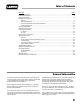
Table of Contents SECTION PAGE General Information . . . . . . . . . . . . . . . . . . . . . . . . . . . . . . . . . . . . . . . . . . . . . . . . . . . . . . . . . . . . . . . . . . .3 Heater Specifications . . . . . . . . . . . . . . . . . . . . . . . . . . . . . . . . . . . . . . . . . . . . . . . . . . . . . . . . . . . . . . . . . .4 Safety Precautions . . . . . . . . . . . . . . . . . . . . . . . . . . . . . . . . . . . . . . . . . . . . . . . . . . . . . . . . . . . . . . . . . . . .
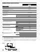
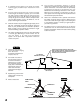
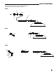
Radiant Heater Specifications Model I5 SPECIFICATIONS Maximum Input (Btuh) 5,200 Ventilation Air to Support Combustion 61 CFM Zone Control Full Output Pressure 5 PSIG Zone Control, Low Fire Pressure 10 - 12 in. W.C. Heater Dimensions (See Fig. 1) “A” 11 3/8 in. “B” 6 1/2 in. “C” 4 1/2 in. Net Weight 1 lb.11 oz. Fuel Consumption Per Hour .24 lbs./hr.
Safety Precautions WARNING Asphyxiation Hazard ■ Do not use this radiant heater for heating human living L.B. White Company to determine combustion air quarters. ventilation requirements of the heater. ■ Do not use in unventilated areas. ■ The flow of combustion and ventilation air must not be obstructed. ■ Lack of proper ventilation air will lead to improper combustion. ■ Proper ventilation air must be provided to support the combustion air requirements of the heater being used.
Safety Precautions 1. Do not attempt to install, repair or service this heater or the gas supply line unless you have continuing expert training and knowledge of gas heaters. Qualifications for service and installation of this equipment are as follows: QUALIFICATIONS FOR SERVICING AND INSTALLATION: a.
14. A qualified service person shall inspect the heater and its gas train at least on an annual basis. This should consist of, but is not limited to, the following points of action: -- Thorough inspection of the heater’s component parts for corrosion, stripped threads, etc. with subsequent parts replacement as necessary. -- Gas pressure checks. -- Start-up and shut down of the heaters and zone control panel to test for proper operation. 15. Turn off the gas supply when the heater is not in use.
13. The corrosive atmosphere present in animal confinement buildings can cause component failure or heater malfunction. The heater should be periodically inspected and cleaned in accordance with the Maintenance and Cleaning Instructions in this manual. Make sure that livestock is protected by a back up alarm system that limits high and low temperatures and also activates appropriate alarms. 9. A qualified service agency must check for proper operating gas pressures upon installation of the heaters. 10.
GAS TRAIN ASSEMBLY Your heater is supplied with one of the following gas train assemblies. Refer to the appropriate illustrations. FIG. 3 STANDARD HOSE BUSHING RIGID END OF HOSE TO GAS SUPPLY CONNECT HOSE TO CONTROL VALVE INLET, TIGHTEN SECURELY VALVE, SHUT-OFF 1/8 NPT FITTING KIT, PART #23406 FIG. 4 A B STEM FITTING ASSEMBLY NUT CONTROL VALVE INLET - ASSEMBLE FITTING - ATTACH FITTING TO CONTROL VALVE INLET & TIGHTEN SECURELY.
ZONE CONTROL PANEL COMPONENT FUNCTION AND INSTALLATION The zone control panel is a remote mounted control system. It allows non-electrical, modulating , thermostatically controlled operation for a specific quantity of heaters within a heating zone. The panel will control the following quantity of heaters depending on fuel type. Modulating System I5 L. P.
Start-Up Instructions 3. WARNING Fire or Explosion Hazard ■ Do not force the safety control valve button. ■ Use only your hand to depress the gas control button. Never use any tools. Fully depress the button on the safety control valve while applying flame to the inner cone point. Keep the button fully depressed for about 30 seconds until the inner cone stays lit. Allow outer combustion cone to heat up completely.See Fig.8. FIG.
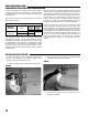
Cleaning Instructions FIG. 9 CAUTION ■ Disinfectants utilized in agricultural animal confinement buildings may contain chemicals damaging to components of the heater. ■ Protect the safety gas control valve and pressure valve by wrapping these components with a plastic bag before disinfecting. ■ Always make sure to remove the plastic bag or other protective covering before start up. Clean the heater on a regular basis to maintain proper combustion and to eliminate future problems.
faucet pressure only, spray water against the cones to wash out the build up of dust in the cones and the venturi tube. Work your way around the entire cone assembly. 3. Run water down through the elbow and out through combustion cones. 4. Repeat steps 2 and 3 until water runs clean. 5. Remove the plastic bag. Inspect the cones and venturi tube to make sure these areas are clean. 6. Return the heater to its original hanging position. 7.
Maintenance Instructions 1. Have your gas supplier check all gas piping annually for leaks or restrictions in gas lines. Also, at this time have your gas supplier clean out the sediment trap on the zone control panel of any debris that may have accumulated. 2. The heater’s surrounding area shall be kept clear and free from combustible materials, gasoline, and other flammable vapors and liquids. 3. Regulators can wear out and function improperly.
SAFETY GAS CONTROL VALVE AND BURNER ORIFICE 1. Disconnect the gas hose. FIG. 11 2. Remove the thermocouple from the safety control valve. SCREW FILTER HOLDER 3. Remove the filter (if necessary) and the screw on filter holder. 4. Pull safety control valve from venturi tube. 5. Using a 6 mm hex nut driver, remove orifice and clean if necessar y. When reinstalling, do not overtighten as thread damage may occur. ORIFICE THERMOCOUPLE 1. Remove the thermocouple bracket nut from its mounting stud. See Fig.
THERMOSTATIC HEAD ( Located on Modulating Zone Panels) The head assembly includes the adjustable thermostatic head, capillary and sensor. The part number for the assembly is 09416 ( w/26 ft. capillary). FIG. 13 THERMOSTATIC HEAD THERMOSTAT HEAD & CAPILLARY 400-09416 ATTACHMENT KNOB Replacement would be needed if damage occured due to: -- Careless handling during installation, cleaning or servicing. -- Locating the sensor and capillary too close to floor or ground level, allowing contact with livestock.
Troubleshooting Guide READ THIS ENTIRE SECTION BEFORE BEGINNING TO TROUBLESHOOT PROBLEMS. The following troubleshooting flow charts provide systematic procedures for isolating heater problems. The charts are intended for use by a QUALIFIED GAS HEATER SERVICE PERSON. DO NOT SERVICE THE HEATER UNLESS YOU HAVE BEEN PROPERLY TRAINED. WARNING Burn Hazard ■ Troubleshooting this system may require operating the heater with the burner on. Use extreme caution when working on the heater.
Heater Backflashes Gas Through IAir Inlet. Problem 2 Yes No Is Proper Gas Pressure Yes Being Supplied to the Heater? Open All Fuel Supply Valves. No Are all Fuel Supply Valves to Heater Open? Check for Proper Gas Pressure. Proper Pressure at High Heat Should Read 5 PSIG. Inner Combustion Cone Will Not Light Problem 1 Yes Clean These Areas.
No Is Button on Safety Control Valve Fully Depressed? Yes Yes Yes Check Gas Pressure to the Heater Inlet with a Gas Gauge. Proper Pressure at High Heat Should Read 5 PSIG. Low Heat is 10 in. W.C. No Yes Is Safety Control Valve Defective? No Is Thermocouple Defective? Remove the Component and Clean It. Yes Yes Check Millivolt Output of Thermocouple with Millivolt Test Kit. Output Should be at Least 4 mv D.C. A Reading of Less Than 4 mv D.C. Can Cause Inner Cone to Go Out.
Yes No No Is Burner Orifice Plugged? Remove the Component and Clean It. Yes Remove Orifice and Clean It. B. Replace Thermostatic Head Valve Body. -- OR -- A. Remove Thermostatic Head from Thermostatic Valve Body. on Zone Panel. If Outer Cone Lights, Replace Thermostatic Head and Sensor Assembly. Yes Does Main Burner Shut Off When Thermostatic Head is Set Below Room Temperature? Check for Proper Gas Pressure to the Heater. Proper Pressure at High Heat Should Read 5 PSIG.
Heater Component Function Burner Orifice Metering device used to feed gas to combustion cones at a specific flow rate. Canopy Reflective aluminum heat shield for heater. Combustion Cones Made of special alloy steel. This is where combustion of gas occurs, providing radiant heat used in the warming process. Gas Hose Flexible connector used to convey gas from gas supply line to inlet of heater.
Parts Identification PARTS SCHEMATIC 12 11 7b USED ONLY ON HEATERS WITH SERIAL NUMBER Z147800 AND LATER 9 16 15 14 3 4 1 10 6 2 7a 13 5 7b 7c 8 7d 7b 7e 22
PARTS LIST Item 1 Description Hose,6 ft. Male Quick Coupling End 10 ft. Male Quick Coupling End 15 ft. Male Quick Coupling End 6 ft. Standard (Rigid by Swivel) 10 ft.Standard( Rigid by Swivel) 15 ft. Standard (Rigid by Swivel) 6 ft. Double Swivel Ends 6 ft. Male End by Swivel w/ Quick Coupling Kit 10 ft.
Warranty Policy EQUIPMENT L.B. White Co., Inc. warrants that the component parts of its equipment are free from defects in material and workmanship, when properly installed, operated, and maintained in accordance with the Installation and Maintenance Instructions, safety guides and labels contained with each unit. If, within 12 months from the date of purchase by the end user, any component is found to be defective, L.B. White Co., Inc.