Pilot Light Ignition Agricultural Animal Confinement Building Heaters Installation and Service Guide 150-22003
Foreword The purpose of this Service Guide is to provide detailed instructions and information for the installation, maintenance, troubleshooting and repair of L.B. White pilot ignition agricultural heaters. By consulting specific sections within the guide, you will become acquainted with components and operation of the equipment as well as proper procedures to use during trouble analysis and repair. Parts illustrations and information for all L.B. White pilot ignition heaters is included.
GENERAL HAZARD WARNING ■ Failure to comply with the precautions and instructions provided within this guide, can result in: — Death — Serious bodily injury or burns — Property damage or loss from fire or explosion — Asphyxiation due to lack of adequate air supply or carbon monoxide poisoning — Electrical shock ■ Read this Service Guide before installing or servicing this heater. ■ Only properly-trained service people should repair or install L.B. White heaters.
Table of Contents Section 1 General Information Section/Page Basic Unit Description and Application . . . . . . . . . . . . . . . . . . . . . . . . . . . . . . . . . . . .1.1 Key Markings; Purpose and Location . . . . . . . . . . . . . . . . . . . . . . . . . . . . . . . . . . . . . .1.1 Heater Specifications . . . . . . . . . . . . . . . . . . . . . . . . . . . . . . . . . . . . . . . . . . . . . . . . . . .1.2 Safety Precautions . . . . . . . . . . . . . . . . . . . . . . . . . . . . . . . . . . . . . .
General Information Basic Unit Description and Application Pilot ignition agricultural building heaters are direct-fired, non-vented heaters used in the heating of animal confinement buildings (examples: swine, chicken, and turkey). These heaters utilize a system that ignites the gas by a conventional pilot flame rather than by direct spark or a hot surface igniter. L.B. White offers you the most dependable pilot system in the industry.
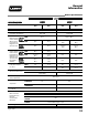
General Information Heater Specifications Model SPECIFICATIONS 346 Heaters Using Control Valves Less Internal Low Pressure Regulator and Gas Shut Off (Control Valve Part #50002309) Inlet Gas Supply Pressure 760 CFM 10.5 in. W.C. 7.0 in. W.C. 11.0 in. W.C. 7.0 in. W.C. 1.2-1 1 N/A 11.0 in. W.C. 7.0 in. W.C. N/A N/A N/A N/A 3.6 in. W.C. 11.5 in. W.C. 4.5 in. W.C. 11.5 in. W.C. 4.5 in. W.C. 11.5 in. W.C. 3.6 in. W.C. MIN. 11.5 in. W.C. 3.6 in. W.C. 11.5 in. W.C. 4.5 in. W.C. 11.
General Information Heater Specifications Model AB200 SPECIFICATIONS L.P. Gas Natural Gas Maximum Input (BTUH) Minimum Input (BTUH) Ventilation Air Required to Support Combustion Heaters Using Control Valves With Internal Low Pressure Regulator and Gas Shut Off Heaters Using Control Valves Less Internal Low Pressure Regulator and Gas Shut Off (Control Valve Part #50002309) Inlet Gas MAX. Supply Pressure MIN. 200,000 N/A 250,000 160,000 760 CFM 1100 CFM N/A 13.5 in. W.C. 11.5 in. W.C. 7.0 in. W.
General Information Safety Precautions WARNING ■ ■ ■ ■ ■ Asphyxiation Hazard the L.B. White Company to determine combustion air Do not use this heater for heating human living quarters. ventilation requirements of the heater. Do not use in unventilated areas. ■ Lack of proper ventilation air will lead to improper The flow of combustion and ventilation air must not be combustion. obstructed.
General Information Safety Precautions 1. Do not attempt to install, repair, or service this heater or the gas supply line unless you have continuing expert training and knowledge of gas heaters. Qualifications for service and installation of this equipment are as follows: a. To be a qualified gas heater service person, you must have sufficient training and experience to handle all aspects of gas-fired heater installation, service and repair.
General Information Safety Precautions three-prong receptacle. Failure to use a properly grounded receptacle can result in electrical shock, personal injury, or death. 14. If gas flow is interrupted and flame goes out, do not relight the heater until you are sure that all gas that may have accumulated has cleared away. In any event, do not relight the heater for at least 5 minutes. 1.4-3 3 15.
Installation Instructions General Information WARNING Fire or explosion hazard. Can cause property damage, severe injury or death. ■ Disconnect power supply before wiring to prevent electrical shock or equipment damage. ■ To avoid dangerous accumulation of fuel gas, turn off gas supply at the appliance service valve before starting installation, and perform gas leak test after completion of installation. ■ Do not force the gas control knob. Use only your hand to turn the gas control knob.
Installation Instructions Pipe Sizing GENERAL INFORMATION c. The information in the pipe sizing tables was obtained from Engineered Control International, Inc., L.P. Gas Serviceman’s Manual L545. Pipe sizing is critical to the proper operation of any gas heating system. However, piping is dependent on several factors: d. Do not attempt gas supply line selection or installation unless you are properly trained and qualified. 1. Total gas load expressed in BTUH. 2.
Installation Instructions Pipe Sizing EXAMPLE (Refer to Fig 2) IMPORTANT: If exact length is not on chart, use next longer length. Select the size of pipe that shows at least as much capacity as needed for each piping section. c. Section C to D must supply a load of 750,000 BTUH. Select 3/4 inch pipe for Section C to D. d. Section D to E must supply a load of 500,000 BTUH. Select 1/2 inch pipe. a. Section A to B of pipe must supply the complete gas load of 1,500,000 BTUH for the entire building.
Installation Instructions Tank Sizing pressure washers, water heaters, etc., that will be drawing vapor from the tanks. ATTENTION ■ The following is supplied for informational purposes only. ■ Consult your LP gas supplier for specific requirements. A tank is propane storage container ranging in size from 150 gallons to 10,000 gallons or larger. For agricultural heating applications, the tank sizes typically used are either 500 gallons or 1,000 gallons with 1,000 gallons being the most common.
Installation Instructions Tank Location and Installation ATTENTION ■ The following is supplied for informational purposes only. ■ Tank installation shall only be accomplished by a qualified LP gas installation person. ■ State and local codes must be observed at all times. ■ In absence of state and local codes, follow ANSI/NFPA58 Standard for Storage and Handling of Liquefied Petroleum Gases.
Installation Instructions LP Gas Tank Manifolding ATTENTION ■ The following is supplied for informational purposes only. ■ Tank manifolding shall only be accomplished by a qualified LP gas installation person. ■ Local and state codes must be observed at all times. ■ In absence of state and local codes, follow ANSI/NFPA58 Standard for Storage and Handling of Liquefied Petroleum Gases.
Installation Instructions Manual Shut-Off Valve, Hose and Regulator Assembly 1. Always use approved pipe thread compound suitable for use with L.P. gas or natural gas on the threaded connections. 2. Assemble the components together according to the figure. This view is to show general assembly of the components only. 6. The heater’s gas regulator (with pressure relief valve) should be installed outside of building. Any regulators inside the buildings must be properly vented to the outside.
Installation Instructions Sediment Trap Assemble the tee, nipples and cap together and tighten securely. The sediment trap assembly must always be mounted in a vertical position. Make sure pipe thread compound that is resistant to both L.P. gas and natural gas is used in making all connections. Check all connections for gas leaks using approved gas leak detectors.
Installation Instructions Electrical Requirements ATTENTION ■ The following is supplied for informational purposes only. ■ All electrical wiring shall be accomplished by a qualified electrician. ■ Local and state codes must be observed at all times. ■ In absence of local or state codes, follow ANSI/NFPA70 National Electrical Code. Strict attention must be given to the following areas before connecting the heater to its electrical supply.
Installation Instructions Remote Thermostat Models 346/348, 377/379, 408/410 1. Disconnect the heater from its electrical supply and close all fuel supply valves to the inlet of the heater. 2. Locate the two wires labeled “power supply to thermostat” and “power return from the thermostat” within the heater’s electrical junction box. Black Lead 7. Connect the white lead of the thermostat cord to the lead labeled “power return from thermostat”. Twist a wire nut onto the exposed lead conductors until tight.
Installation Instructions Remote Thermostat Models 346/348, 377/379, 408/410 (Cont.) 9. Reconnect the heater to its electrical supply and open the fuel supply valves to the inlet of the heater. 10. Light the pilot. Turn the thermostat up above room temperature so the motor starts and main burner ignites. Check the heater for proper operation. 11. Install the junction box cover plate. Tighten the plate screws securely. 4.
Installation Instructions Remote Thermostat Model AS040 (Cont.) Model AB200 and AB250 7. Attach the ground lead terminal to the ground screw in the enclosure. 1. Disconnect the heater from its electrical supply and close all fuel gas valves to the inlet of the heater. 2. Open the burner access door to locate the heater’s electrical enclosure. Remove the cover from the enclosure. Ground Lead 8.
Installation Instructions Remote Thermostat Model AB200 and AB250 5. Secure the cord in place at the entry hole on the case front with the strain relief provided in the thermostat kit. 6. Loosen the terminal strip screws that hold the jumper in place. Remove the jumper. 7. Push the exposed conductors of the power supply and power return leads beneath the terminal strip screw plates previously occupied by the jumper.
Installation Instructions Hanging Instructions 1. Assemble according to the illustration and tighten all eyebolts securely. 2. Make sure the heater is properly positioned before use and is hung level. Observe and obey all minimum safe distances of the heater to the nearest combustible materials. Minimum safe distances are given on the heater dataplate. 3. See figure for typical indoor installation.
Installation Instructions Air Diverters Depending on model number, two designs of air diverters may be available for your heater. The air diverters allow the hot discharge air to be blown out either in two 45 degree paths or in one direction only (two-piece diverter kit only). Either way promotes good air movement and circulation. Two-P Piece Air Diverter 1. Install the air diverter as follows. This is a typical procedure for all heaters. Appearance of the outlet on heater may vary from model to model.
Installation Instructions Air Diverters One-P Piece Air Diverter 1. Loosen the four blower outlet screws. 2. Align the keyhole slots in the mounting flanges with each outlet screw. Keyhole Slots 2.11-2 2 3. Push down on the diverter to lock it into position. Tighten the outlet screws. ATTENTION Larger design air diverters for Models 377/379, 408/410, and AB200 heaters incorporate holes in the “Y” of the assembly to allow ease of mounting to the heater outlet.
Operation Instructions Start-Up and Shut-Down Instructions Start-U Up Instructions Determine the pilot control valve type supplied on the heater. For heater with gas control valves with an internal low pressure regulator and gas shut off, refer to Section A. For heaters with gas control valves without an internal low pressure regulator and gas shut-off, refer to Section B.
Operation Instructions Start-Up and Shut-Down Instructions Shut-D Down Instructions If the heater is to be shut down for cleaning, maintenance, or repair, follow steps 1 through 5. Otherwise, simply turn the thermostat to “Off” or “No Heat” for standard shut down. 1. Close all manual fuel supply valves. 2. With heater lit, allow heater to burn off remaining fuel in gas supply hose. 3.1-2 2 3. If applicable, turn the control valve knob to “Off”. 4. Turn thermostat to “Off” or “No Heat” position. 5.
Operation Instructions Variable Heat Output 1. Some models of propane (LP) gas or natural gas heaters have a throttle valve for varying heat output located between the gas control valve and gas manifold assemblies. THIS IS NOT A MANUAL GAS SHUT OFF VALVE. 2. The throttle valve can be adjusted to deliver either minimum heat or maximum heat. Become familiarized with the design of the throttle valve in your heater.
Preventative Maintenance Periodic Inspection 1. The area surrounding the heater shall be kept clear and free from combustible materials, gasoline, and other flammable vapors and liquids. regulators installed and check delivery pressures to the appliance to make sure that the regulator is reliable. 2. Have your gas supplier check all gas piping annually for leaks or restrictions in gas lines. Also, at this time have your gas supplier clean out the sediment trap of any debris that may have accumulated. 5.
Preventative Maintenance Cleaning Instructions WARNING Fire, Burn, and Explosion Hazard ■ This heater contains electrical and mechanical components in the gas management, safety and airflow systems. ■ Such components may become inoperative or fail due to dust, dirt, wear, aging, or the corrosive atmosphere of an animal confinement building. ■ Periodic cleaning and inspection as well as proper maintenance are essential to avoid serious injury or property damage. 1.
Troubleshooting Instructions Troubleshooting Guide READ THIS ENTIRE SECTION BEFORE BEGINNING TO TROUBLESHOOT PROBLEMS. WARNING Electrical Shock and Burn Hazard ■ Do not attempt to service or repair this heater unless you are a properly trained and qualified gas heater service person. To effectively use these flow charts, you must first identify the problem. The problems are numbered sequentially, along with a brief explanation of each problem.
Troubleshooting Instructions Troubleshooting Pilot Flame ATTENTION ■ These illustrations are intended to provide a means to assist you in troubleshooting a pilot problem. They must be used in conjunction with proper cleaning, checking for proper gas pressures, etc. 1. Correct Flame ■ With any pilot light assembly, always make sure the thermocouple is completely installed within the pilot bracket by either its mounting clip or nut. 4.
August 1999 5.1-3 3 Pilot will not light. Problem 1 Fill container if low. No Is LP gas cylinder or tank full? Yes Open all supply valves. No Are all fuel supply valves open? Yes Fully depress the pilot button. No Is the pilot control button fully depressed? No Yes Is there a restriction in gas Yes supply hose, pilot tube or pilot orifice? Replace pilot No Is the correct pilot orifice installed for the fuel being used? Remove these components and blow out with compressed air.
5.1-4 4 August 1999 Pilot will not stay lit when pilot control button is released. Problem 2 No No Yes Check for proper pressure to heater inlet. Refer to heater nameplate. No Replace with proper pilot orifice. No Is proper pilot orifice installed? No Yes Check millivolt output. 10 MV or greater is acceptable. Replace thermocouple if less than 10 MV (with burner off). Yes Yes No Has drop out of safety magnet on pilot control been checked? Pilot flame should impinge on 3/8 - 1/2 in.
August 1999 5.1-5 5 Yes No Is proper voltage supplied to and from high limit switch to control valve? No Are burner orifice, burner Yes casting or manifold plugged? No Is high limit switch tripped? Yes Yes Check for proper pressure using low pressure gas gauge. Refer to heater nameplate. No Yes Replace air proving switch or for units with centrifugal switch, replace motor. No Are air proving switch or centrifugal switch contacts opening and closing properly? (Perform a continuity check.
5.1-6 6 Motor does not run, heater does not light with pilot light lit. Problem 4 August 1999 Yes Provide proper voltage. See heater nameplate. Check circuit breaker in electrical system. No Is proper voltage supplied to heater power cord? Yes Set thermostat above room temperature. No Is thermostat set above room temperature? Yes Check electrical connections to thermostat and power cord. No Is proper voltage supplied to thermostat? Yes Defective thermostat. Replace.
August 1999 5.1-7 7 Pilot light will not stay lit when main burner and blower are operating. Problem 6 Main burner cycles on and off repetitively. Pilot stays lit. Problem 5 Yes Check for proper pressure. Make sure proper fuel is being used for appliance installed. No Have you checked for proper fuel use and inlet gas pressure? Remove blockages. No Is outlet of heater free from blockages? Yes Air proving switch arm is out of adjustment.
5.1-8 8 August 1999 High limit switch is open. Problem 7 Give heater a thorough cleaning with a soft brush or compressed air. DO NOT USE WATER OR ANY LIQUID CLEANING AGENTS. No Is heater reasonably clean? No Is fan loose or dirty? Yes Yes Yes No Have you checked for proper gas type being used, pressure or for liquid propane in line? No On heaters without air proving switch, is motor overheating and shutting down? Remove restriction.
August 1999 5.1-9 9 Burner flame drops out after 10 - 15 minutes of Problem 10 Flame “lifting” off of burner. Problem 9 Burner does not shut off when temperature requirement is satisfied. Problem 8 Yes Yes Yes Resize line and reselect larger tank size if necessary. No Is gas supply line and tank properly sized? Check for proper pressure to inlet of heater and also for proper burner manifold pressure. No Has gas pressure been checked? Replace thermostat.
5.1-1 10 August 1999 Motor “hums”. Problem 12 Gas control valve “chatters”. Problem 11 Yes Defective motor or capacitor. Replace. No Are wires disconnected between motor and capacitor? Check for proper voltage. See heater nameplate. Have qualified electrician correct if necessary. No Is proper voltage to gas control valve being supplied? Yes Yes Defective gas control valve solenoid. Replace entire valve. Reconnect wires. Test for proper operation.
August 1999 5.1-1 11 Yes Is the gas control valve receiving proper inlet pressure and delivering proper outlet pressure? Is heater receiving proper voltage from power supply? (check heater dataplate.) No Is blower outlet blocked? Yes Yes Is burner orifice or casting plugged with dust or debris? Yes Clean with soft brush, dry cloth or compressed air. Defective motor or capacitor. Replace motor. Remove blockage(s). Clean heater as necessary.
Voltage Checks Procedure Checking for voltage supply to high limit switch. Testing for voltage at any of the components is a relatively easy procedure. The following illustrates how to check voltage at some of the components used in the heater. Apply the probe to the power input side of the limit switch and the other to ground. Voltage will appear after the air proving switch makes. Warning Electrical Shock Hazard ■ Troubleshooting may require the heater to be connected to its electrical supply.
Component Testing Continuity Checks Continuity Checks High Limit Switch Equipment required: Digital Volt/Ohm Meter Explanation: In a continuity test, you simply want to determine whether or not an electrical pathway exists through a component. For these tests, it is important that the probes of the multimeter make good contact with the part being tested. They should touch bare metal or wire, not insulation, paint, or dirt. Alligator clips make firmer contact than needle probes, use them where possible.
Component Testing Continuity Checks Thermostat Attention ■ Many thermostats can be wired to open or close on an increase in temperature. ■ Make sure the thermostat is wired properly so the contacts close when the thermostat is set to a point above room temperature and open when the temperature is achieved. This will allow the heater to cycle accordingly. ■ Refer to the heater wiring diagram or the wiring diagram applied to the inside of the thermostat cover for proper connection. August 1999 6.
Component Testing Thermocouple and Power Unit Tests PILOT BURNER Equipment Required: THERMOCOUPLE Volt / Ohm Meter with DC Scale Thermocouple Test Kit, Part Number 500-08506 The thermocouple is used in conjunction with the pilot safety control valve in supplying pilot gas to the pilot orifice. THERMOCOUPLE LEAD Here is How it Works: A thermocouple converts heat energy into electrical energy.
Component Testing Thermocouple and Power Unit Tests Testing Procedures: C. THERMOCOUPLE CHECK (Applies to all thermocouples and gas control valves.) A. INITIAL PREPARATION 1. Disconnect the heater from its electrical supply. 1. Light the pilot. 2. Set your voltage tester to the DC scale, and if the tester is so equipped, set the scale to MV (millivolts). Connect the probes of multimeter to the millivolt tester. 2. Close the fuel supply valves to the inlet of the heater. B. TEST KIT INSTALLATION 1.
Component Testing High Limit Switch Tests Method of Test: Disconnect the heater from its electrical supply before conducting this test. Remove the switch from its location. Hold the switch by one of its legs with a pliers and apply a small flame only to the sensing portion on the back side of the switch. Be careful not to melt the plastic housing of the switch when conducting this test. Within 1 minute, you should hear a “pop” coming from the switch which indicates the electrical contacts have opened.
Wiring Diagrams Electrical Connection and Ladder Diagram The wiring diagram on the following page is provided to give the qualified service person information on the interconnection and sequence of operation of the electrical components of various models of L.B. White pilot ignition heaters. The wiring diagram is generic in its design and is suitable for all models and designs of L.B. White pilot ignition heaters.
Electrical Connection and Ladder Diagram Wiring Diagrams Used on: Design Sequence All Model All WARNING: THIS HEATER MAY START AT ANY TIME AIR PROVING SWITCH (NOT SUPPLIED ON SOME MODELS) BLACK OR RED BLACK BLACK OR RED BLACK BLACK GAS CONTROL WHITE VALVE HIGH LIMIT SWITCH BLACK BLACK THERMOSTAT (OPTIONAL) JUMPER (REMOVE TO ADD THERMOSTAT) BLACK MOTOR WHITE BLACK WHITE POWER GREEN CORD GROUND NOTE: IF AIR PROVING SWITCH IS NOT SUPPLIED, POWER IS SENT DIRECTLY TO HIGH LIMIT SWITCH.
Servicing Instructions Component Identification and Function All components must work together for proper heater operation. However, as with anything electrical or mechanical, problems may arise which will require you to determine what malfunction has occurred. Before you start troubleshooting, it’s a good idea to understand the components in their appearance and purpose. Main Operational Components A.
Servicing Instructions Component Identification and Function E. Fan Housing An assembly composed of the motor, fan wheel and housing for purposes of pulling air through the heater and discharging heated air into the room. F. Fan May be of blade or wheel designs depending on heater model. Used in conjunction with the motor and fan housing to pull hot air from the heater and blow it into the room for heating purposes. G.
Servicing Instructions Component Identification and Function I. High Limit Switch A manually resetable temperature activated switch. Its purpose is as a safety device wired into the control system to sense when an overheat condition occurs, either at the heat chamber or blower outlet. The switch “opens” the electrical circuit to the gas control thereby shutting off gas flow.
Servicing Instructions Component Identification and Function N. Pilot Safety Control Valve A gas control valve which is held open by electrical power supplied by a pilot generator and which closes automatically to shut off the flow of gas to the main burner when the pilot flame is extinguished or becomes too small to light the main burner. Additionally, it consists of electrical solenoids which are used for the control of gas flow to the main burner.
Servicing Instructions Model AS040 Fan and Motor Cleaning the Fan: 1. Disconnect the heater from its electrical supply and close all fuel supply valves to the heater. 5. Clean the fan with a soft brush, rag, or compressed air. 2. Remove the motor access panel on the case back. 3. Disconnect the motor wires from the terminal strip. 4. Remove the screws that hold the motor mount to the heat chamber. Pull the fan and motor assembly from the heater.
Servicing Instructions Model 377/379 Fan and Motor Cleaning and Replacing the Fan: 1. Disconnect the heater from its electrical supply and close all fuel supply valves to the inlet of the heater. 2. Remove the access panel at the end of the heater opposite burner. 5. Pull the fan wheel from the motor shaft. Use a wheel puller if necessary. All L.B. White fan wheels incorporate a wheel puller groove on the fan hub to assist in fan removal. 3. Remove the air inlet ring screws. 6.
Servicing Instructions Models 346/348, 408/410, AB200, AB250 Fan and Motor Cleaning the Fan: 1. Shut off the gas supply to the heater and disconnect the heater from its electrical supply. 4. Remove the screws that secure the motor mount plate to the fan housing. 2. Open or remove the access panel on the end of heater opposite burner. 5. Lift and pull the motor and fan assembly from housing. 3. Disconnect the motor leads. 6.
Servicing Instructions Air-Proving Flapper (Sail) The flapper is located in the blower outlet. As discussed in Section 9.1, Component Identification and Function, its purpose is to assist the air-flow switch in establishing proper air pressure and, therefore, fan speed is achieved before the gas valve opens. However, over a period of time, the flapper may accumulate deposits of dust or dirt affecting its ability to pivot, thereby creating system failures.
Servicing Instructions Air-Proving Switch For Units With Flapper: 1. Shut off gas supply and disconnect heater from electrical source. 2. Disconnect air-proving switch leads. Make sure on reassembly that two nuts per screw are used as spacers between the switch and housing side panel. These nuts are tightened securely against the housing side panel. Slide the switch onto the screws and secure the switch in place using the two remaining nuts. 3.
Servicing Instructions Pilot Assembly CAUTION 4. Clean the pilot assembly using a soft brush or compressed air. Allow the pilot assembly to cool before servicing. 1. Disconnect the heater from its electrical supply and close all fuel supply valves to the heater. 2. Open the burner end access door or remove the access panel. 3. Remove the screw(s) that secure the pilot assembly to the burner. 5.
Servicing Instructions Pilot Assembly 6. Pilot orifices may incorporate one or two holes, depending on design. Hold the orifice up to light to make sure the orifice is clear of blockages. 8. Reverse these procedures to reinstall the orifice, pilot line and shield. ATTENTION Holes For Heaters so Equipped: ■ Use care when servicing the pilot assembly to prevent damage to the pilot gasket.
Servicing Instructions Thermocouple CAUTION 4. Remove the connector nut at the power unit on the gas control valve. Allow the pilot assembly to cool before servicing. 1. Disconnect the heater from its electrical supply and close all fuel supply valves to the heater. 2. Remove the screw(s) that secure the pilot assembly to the burner. Nut 5. To reassemble, reverse these procedures. 3.
Servicing Instructions Thermocouple ■ Do not use pliers when removing or tightening the ■ Insure the thermocouple is fully and firmly ■ Insure dirt or debris has not fallen into the power ■ Do not make sharp kinks or bends in the attachment nut or connector nut. Doing so will round off the nuts creating service problems. unit prior to thermocouple installation. Dirt and debris will block the electrical pathway of the thermocouple, creating pilot outages.
Servicing Instructions High-Limit Switch Replacement Very little actual servicing of the high-limit switch is required. However, it is good to know the location of the switch when working on the heater. Typically, the switch is located on the heat chamber face or at another similar location at the burner end of the heater. Some models may have the switch located on a bracket near the burner. thickness may vary with model and design. appropriate parts list.
Servicing Instructions High-Limit Switch Replacement Specifically relating to the AB200 heater, the high limit is a capillary and switch mounted to a bracket near the burner. If switch replacement is necessary you will need to route the capillary behind the burner, and then across the heat chamber face, allowing 12 inches of capillary to be in contact with the heat chamber. The capillary is held in position by tabs that are formed from the heat chamber.
Servicing Instructions Burner and Burner Orifice Over a period of time, the burner and orifice may start to become blocked if cleaning is not provided. This can create poor burning of the fuel gas, resulting in nuisance heater problems. Removal of burner and orifice may be required if blockages cannot be removed by general cleaning. If removal is necessary, refer to the following instructions. Familiarize yourself with these procedures before disassembly. 1.
Servicing Instructions Burner and Burner Orifice 7. Remove the two screws and spacers located at the right and left hand top of the burner casting (if applicable). Screw 8. Disconnect the electrical leads, pilot line, and thermocouple from the gas control valve. 9. Remove the burner and valve/manifold assembly from the heater. Some larger models may require you to pivot the valve and manifold assembly to remove the orifice from beneath the burner. 10. Hold the burner casting up to a light.
Servicing Instructions Leak and Gas Pressure Checks Equipment Required: A. Preparation 1 - 3/16 Hex Head Allen Key 1. Make sure all threaded connections to the inlet of the control valve are tightened securely. Obtain two pressure gauges capable of reading up to 35 in. W.C. 2 - Low Pressure Gauge Kits, Part Number 550-00764 2. Disconnect the heater from the electrical supply and close the fuel supply valve to the heater inlet. Certified Leak Detectors 3. Open or remove the burner access panel.
Servicing Instructions Leak and Gas Pressure Checks Gauge Adapter a. Check all pipe connections, hose connections, fittings and adapters upstream of the gas control with approved gas leak detectors. In the event a gas leak is detected, check the components involved for cleanliness and proper application of pipe compound before further tightening. b. Tighten the gas connections as necessary to stop the leak. c.
Servicing Instructions Leak and Gas Pressure Checks D. Reading Pressures 1. With the heater operating, the pressure gauges should read the pressures specified on the dataplate, or in the specification section of this guide. b. Using a standard screwdriver, turn the plastic adjusting screw until the gauge reads proper manifold pressure. Clockwise increases outlet pressure. Counterclockwise will decrease pressure. 2.
Servicing Instructions Leak and Gas Pressure Checks The preceding instructions dealing with inlet and manifold pressure checks and leak testing generally apply to all control valves. However, due to model and age variations of heaters, there are several differences between control valves with which you must be familiar. Pilot Button ■ Part number 500-02309 has burner manifold pressure taps located on either side of the control valve’s main solenoid.
Service Parts, Kits and Accessories Parts Identification Guide The parts identification guides on the following pages have been designed to give a quick reference to component parts used on pilot ignition agricultural building heaters. The guides identify components not only used on current production, but also on equipment that is of earlier design. To use the guides properly, you should know the model numbers of the heater and its design sequence. This information is identified on the dataplate.
Service Parts, Kits and Accessories Parts Identification Guide Model AS040 Item 1 2 3 4 5 6 7 8 9 10 11 12 13 14 15 16 17 18 19 20 21 22 23 24 25 26 27 28 29 30 31 32 33 34 35 36 37 38 39 40 41 Description Regulator, Second Stage, Vent Over Side (LP Gas) Regulator, Single Stage (Natural Gas) Nipple, 1/2 x 3 1/2 Valve, Manual Shut-O Off Hose, 1/2 x 10 ft.
Service Parts, Kits and Accessories Parts Identification Guide 28 Model AS040 31 29 30 27 37 25 24 32 26 33 23 38 34 22 16 35 17 21 11 20 36 14 19 13 18 40 12 15 6 41 39 42 10 9 5 1 INSTALLATION OF GAS TRAIN ASSEMBLY FOR NATURAL GAS ONLY 1 2 3 7 4 8 8 August 1999 7 9.
Service Parts, Kits and Accessories Parts Identification Guide Models 346 and 348 Item 1 2 3 4 5 6 7 8 9 10 11 12 13 14 15 16 17 18 19 20 21 22 23 24 25 26 27 28 29 30 31 32 33 34 35 36 37 (1) (2) (3) N/A Description Regulator, Single Stage (LP Gas) Regulator, Second Stage (LP Gas) Regulator, Single Stage (Natural Gas) Regulator, Second Stage (Natural Gas) Hose, 1/4 in. ID x 10 ft. Hose, 1/2 in. ID x 10 ft.
Service Parts, Kits and Accessories Parts Identification Guide Models 346 and 348 33 32 34 31 30 29 28 27 19 26 17 20 16 22 24 1 9 8 25 36 21 18 9 35 8 1 23 16 14 4 15 13 5 L RA TU PPLY A N TO AS SU G 2 11 12 3 6 2 37 10 SEDIMENT TRAP KIT OPTIONAL ACCESSORY August 1999 4 9.
Service Parts, Kits and Accessories Parts Identification Guide Models 377 and 379 Item 1 2 3 4 5 6 7 8 9 10 11 12 13 14 15 16 17 18 19 20 21 22 23 24 25 26 27 28 29 30 31 32 33 34 35 36 37 38 39 40 41 42 43 44 45 46 47 48 (1) (2) N/A Description Regulator, Single Stage (LP Gas) Regulator, Single Stage (LP Gas) Regulator, Second Stage (LP Gas) Regulator, Single Stage (Natural Gas) Adapter, Hose, 3/8 NPT x 1/2 NPS Adapter, Hose, 1/2 NPT x 1/2 NPS Hose, 1/2 in. ID x 10 ft.
Service Parts, Kits and Accessories Parts Identification Guide Models 377 and 379 35 34 33 36 37 32 31 30 29 24 18 25 20 17 39 28 26 16 1 27 38 19 23 14 41 22 13 10 21 40 15 9 12 AL LY UR PP T U NA S S GA 42 12 11 4 8 2 5 22 1 6 3 7 23 43 47 48 44 13 46 45 August 1999 SEDIMENT TRAP KIT OPTIONAL ACCESSORY 9.
Service Parts, Kits and Accessories Parts Identification Guide Models 408 and 410 Item 1 2 3 4 5 6 7 8 9 10 11 12 13 14 15 16 17 18 19 20 21 22 23 24 25 26 27 28 29 30 31 32 33 34 35 36 37 38 39 40 41 42 43 44 45 46 47 48 49 50 (1) (2) (3) N/A Description Regulator, Single Stage (LP Gas) Regulator, Second Stage (LP Gas) Regulator, Single Stage (Natural Gas) Regulator, Second Stage (Natural Gas) Hose, 1/2 in. x 10 ft. Adapter, 1/2 NPT x 1/2 NPS Valve, Manual Shut Off Nipple, 1/2 in. x 3 1/2 in.
Service Parts, Kits and Accessories Parts Identification Guide Models 408 and 410 41 42 40 39 43 38 47 37 44 33 45 36 22 32 24 46 48 31 20 23 27 34 11 10 21 26 28 25 49 12 8 15 35 1 7 19 9 6 5 16 17 18 14 7 13 4 5 29 30 1 L RA LY TU UPP A N SS GA 2 50 3 SEDIMENT TRAP KIT OPTIONAL ACCESSORY August 1999 9.
Service Parts, Kits and Accessories Parts Identification Guide Model AB200 Item 1 2 3 4 5 6 7 8 9 10 11 12 13 14 15 16 17 18 19 20 21 22 23 24 25 26 27 28 29 30 31 32 33 34 35 36 37 38 39 40 41 42 43 44 Description Regulator, Second Stage (LP Gas) Regulator (Natural Gas) Nipple, 1/2 x 3 1/2 Valve, Manual Shut-O Off Hose, 1/2 in. ID x 10 ft.
Service Parts, Kits and Accessories Parts Identification Guide Model AB200 33 32 31 30 34 35 37 36 44 39 38 40 1 29 28 27 18 25 17 41 L RA LY TU UPP A N SS GA 26 21 19 20 16 2 11 15 3 9 22 14 4 8 13 23 24 10 12 5 42 43 6 7 1 August 1999 9.
Service Parts, Kits and Accessories Parts Identification Guide Model AB250 Item 1 2 3 4 5 6 7 8 9 10 11 12 13 14 15 16 17 18 19 20 21 22 23 24 25 26 27 28 29 30 31 32 33 34 35 36 37 38 39 40 41 42 43 Description Regulator, Second Stage, Vent Over Side (LP Gas) Regulator, Second Stage (Natural Gas) Nipple, 3 1/2 in. Valve, Manual Shut-O Off Adapter, Hose, 1/2 NPT x 1/2 NPS Hose, 1/2 in. ID x 10 ft.
Service Parts, Kits and Accessories Parts Identification Guide Model AB250 33 37 36 38 40 34 35 33 39 41 42 32 43 31 30 29 7 27 26 1 24 28 16 23 15 22 14 21 20 2 25 19 10 13 5 12 18 17 11 45 4 9 August 1999 3 8 6 9.
Service Parts, Kits and Accessories Kits and Accessories This section provides part numbers for many of the more commonly requested kits and accessories used on pilot light ignition heaters.
Service Parts, Kits and Accessories Kits and Accessories TEST KITS PART NUMBER DESCRIPTION 550-00764 Low Gas Pressure Test Kit 550-08506 Thermocouple Test Kit MISCELLANEOUS KITS PART NUMBER 500-07802 DESCRIPTION Indoor Chain Hanging Kit AIR DIVERTERS MODELS PART NUMBER 346, 348 550-07742 AB200, 377, 379, 408, 410 550-07434 AB250 550-20048 346, 348 500-00810 AB200, 377, 379, 408, 410 500-00808 DESCRIPTION Two Piece (Snap-In) One Piece THERMOSTATS DESCRIPTION Remote Thermostat - Penn S
Warranty Guidelines Equipment and Parts EQUIPMENT L.B. White Co., Inc. warrants that the component parts of its heater are free from defects in material and workmanship, when properly installed, operated, and maintained in accordance with the Installation and Maintenance Instructions, safety guides and labels contained with each unit. If, within 12 months from the date of purchase by the end user, any component is found to be defective, L.B. White Co., Inc.
Warranty Guidelines Warranty Returns Warranty Returns To complement L.B. White’s warranty, the following has been written to simplify the warranty return policy. Our goal is to process warranty returns and issue the appropriate credit to you as promptly as possible. Your cooperation in following the procedures listed below will help us achieve our goal. 1. Units and Sub-Assemblies A. Defective heaters and sub-assemblies may be returned to L.B. White by authorized L. B.