
User Manual

IP-00074 Rev. A – 08/06 Page 2 of 3
Installation Instructions
Model: HG5822G
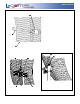
Antenna Components Included:
(2) Antenna Grid Section Halves
(1) Antenna Feed Horn
(2) Mast Clamps
(1) Aluminum “L” Bracket
(6) #M5 Machi ne Screws w/nuts, flat and lock washers
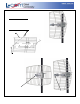
Antenna Assembly Instructions:
Assemble the halves of the Reflector Grid using
(2) #M5 machine scre ws with lock washers, flat
washers and nuts as shown.
Reflector Gri d
Lock Washer & Nut
#M5 Machine Screw
Horizontal
Polarity
Vertical
Polarity
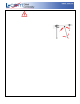
Determine the polarity which will be chosen for the
antenna installation. The antenna can be installed
either vertic ally or horizontally polarized.
The arrow at the end of the
feed horn indicates the
polarity of the antenna.
The two polarities are
illustrated as shown:
Copyright © This drawing is property of L-com Global Connectivity. All rights reserved.
L-COM, INC. 45 BEECHWOOD DRIVE NORTH ANDOVER, MA 01845
WWW.L-COM.COM E-MAIL: SALES@L-COM.COM PHONE: 1-800-343-1455 FAX: 1-978-689-9484
© L-com, Inc. All Rights Reserved. L-com Global Connectivity and the L-com logo are registered marks.