Clarion/Hyperlink Bridge Kit Installation Manual Rev. A Page 1 Hyperlink/Clarion Extended Range Wireless LAN Bridge Kit Featuring the Clarion JX-4000 10 Mbit/sec Wireless Bridge Installation Manual Hyperlink Technologies, Inc.
Clarion/Hyperlink Bridge Kit Installation Manual Rev. A Page 2 Copyright © 1996, Clarion Corporation of America. All rights reserved. No part of the contents of this document may be transmitted or reproduced in any form or by any means without the written permission of Clarion Corporation of America. Portions Copyright © 1998, Hyperlink Technologies, Inc. All rights reserved HyperGain and HyperAmp are trademarks of Hyperlink Technologies, Inc.
Clarion/Hyperlink Bridge Kit Installation Manual Rev.
Clarion/Hyperlink Bridge Kit Installation Manual Rev. A Page 4 Radio Frequency Interference Statement USA - Federal Communications Commission (FCC): This device complies with Part 15 of FCC Rules. Operation of this device is subject to the following two conditions: This device may not cause harmful interference. This device must accept any interference that may cause undesired operation.
Clarion/Hyperlink Bridge Kit Installation Manual Rev. A Page 5 Introduction The Clarion JX-4000 is a wireless transceiver providing 10 Mbit/sec burst data rate to support wireless connections in IEEE 802.3 and Ethernet II (TCP/IP) LAN. Equipped with a Hyperlink Extended Range Amplified Antenna System, the JX-4000 offers an ultra high-performance long-range building-to-building network bridge. The JX-4000 functions as an Ethernet MAU.
Clarion/Hyperlink Bridge Kit Installation Manual Rev. A Page 6 Types of Installations The type of application will determine which type of kit to install: Building-to-Building or Tower-to-Tower: Typically these installations will typically require directional Yagi or Grid Antenna kits. Central Node in a Multipoint Network or Mobile Network: This type of installation typically requires an Omni Directional Kit at the central node for 360 degree coverage.
Clarion/Hyperlink Bridge Kit Installation Manual Rev. A Page 7 complete plug-and-play solution for linking buildings in an outdoor environment. All you need to add is suitable masts or towers and some basic site planning. Please read this manual in its entirety before beginning the installation.
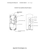
Clarion/Hyperlink Bridge Kit Installation Manual Rev. A Page 8 JX-4000 Front and Rear Panel Features Internal antenna (inside of the top cover) MAU port MAU LED TX LED External antenna port RX LED Power LED DC 6.2V port Power Switch FCC Certification label (bottom) Hyperlink Technologies, Inc.
Clarion/Hyperlink Bridge Kit Installation Manual Rev. A Page 9 Connections and Features of the Amplified Antenna Familiarize yourself with the connections and features of the Amplifier Unit: Mounting Flanges: Two sets of mounting holes are provided on the amplifier’s mounting flanges for either mast mounting using the included U-bolts, or bolted directly to a bracket or other structure.
Clarion/Hyperlink Bridge Kit Installation Manual Rev. A Page 10 The DC Power Injector/ Lightning Protector The DC Power Injector (also known as a "Bias-T") is an in-line device which couples DC power onto a coaxial cable, enabling the cable to carry both RF (radio frequency) signals and DC power. The amplifier is powered remotely through the coaxial antenna feed cable by the way of this device. The DC Power Injector included with the kit also provides integral lightning protection.
Clarion/Hyperlink Bridge Kit Installation Manual Rev. A Page 11 Overall System Configuration The overall system configuration is shown below. Refer to this diagram while reading the section which follows, and during system installation. Antenna Network Hub Transceiver “AUI” Cable Signal Filter DC Power Injector 10BaseT Cable Amplifier Antenna Cable 50ft. JX-4000 Adapter DC Power Cable 4ft. Supply Network Workstation Hyperlink Technologies, Inc.
Clarion/Hyperlink Bridge Kit Installation Manual Rev. A Page 12 ANTENNA SYSTEM CONNECTION Warning The JX-4000 may only be operated using one of the approved antenna kits described herein. All antenna system components are equipped with unique connectors. Although these connectors may look similar to standard types they are not compatible with them. Attempting to attach standard connectors to system components can cause damage to the connectors and attached equipment.
Clarion/Hyperlink Bridge Kit Installation Manual Rev. A Page 13 Preparing for System Installation Warning: These antennas are designed to be mounted in open areas such as rooftops or building exterior walls. They are designed to be installed at least 6 feet away from areas occupied by people. During system operation, always keep the antenna at least 1 foot away from your head. Warning: Before performing the following steps make certain that there are not any power lines within 50 ft.
Clarion/Hyperlink Bridge Kit Installation Manual Rev. A Page 14 layer slightly to ensure a weather-tight seal. 5. Attach the one end of the antenna ground cable to the antenna mounting bracket or V-bolt and the other end to a building ground. 6. Very carefully raise the mast and loosely secure it with the mast mounting hardware. Use the plastic wire ties to tie the antenna cable to the mast every six to twelve inches. 7. Aim the directional antenna in the direction of the building you will be linked to.
Clarion/Hyperlink Bridge Kit Installation Manual Rev. A Page 15 Basic System Checks Using the system’s diagnostic LEDs, some basic system checks can now be performed. When the power is applied to the amplifier, the Power/Transmit indicator LED (found on the bottom corner of the amplifier) glows green. the Power Indicator LED on the DC Power Injector/ Lightning Protector will also illuminate green. When the system is transmitting the amplifier’s LED flashes from green to red/orange.
Clarion/Hyperlink Bridge Kit Installation Manual Rev. A Page 16 JX-4000 LED Diagnostic Display During power-up, the front panel LEDs on the JX-4000 provide some diagnostic information. Refer to the table below for LED diagnostic information. Label MAU TX Color Green Red RX Green Power Red Description Indicates MAU signal (upload or download) is active. 1.
Clarion/Hyperlink Bridge Kit Installation Manual Rev. A Page 17 JX-4000 Specifications Frequency Range: 2400-2483.5 MHz ISM band Carrier Frequency: 2436.07 MHz Modulation Type: Direct Sequence Spread Spectrum Chip Modulation: BPSK, 32 Mcps Processing Gain: 12dB (Nominal) Communication Method: Half Duplex Channel Access Method: SS-P-CSMA1 Type of Interface: MAU (driven by AUI) Datalink Interface: IEEE802.
Appendix A Antenna Mounting Instructions
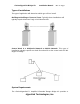
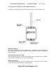
Mounting Instructions - HG2408U Omnidirectional Antenna The included bracket should be used to attach the antenna to a standard antenna mast or tower leg. Proper positioning of the brackets is shown in the following diagram. For best results, first attach the bracket to the tower or structure using the included Vbolt. Then, install the antenna into the bracket and lock in place with the integral bolt.
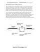
Mounting Instructions - HyperGain HG2414Y Directional Yagi Antenna Yagi antennas are mounted using the included U-Bolts, Nuts, and Lock Washers as shown in the following illustration: The antenna should be aimed as shown, in the direction of the other end of the wireless link.
Mounting Instructions - HyperGain HG2415Y Radome Enclosed Yagi Antenna The antenna can be mounted to a mast or directly to an exterior wall as shown. The included U-bolts should be used for mast mounting. Note that in either case, the metal backing plate should be placed directly behind the plastic flange in order to provide greater stability.