L.L.LF. INDUSTRIES, INC Manufacturer of Steel Doors and Frames, Wood Doors and Hardware installation Procedures Hanging of Doors Painting Hollow Metal Doors and Frames For Help...
INSTALLATION OF FRAMES A. GENERAL Welded door frames are checked at the factory to ensure that they are square and that no jamb twists have occurred during fabrication. Temporary steel spreaders are then attached to the jamb base fo minimize misalignment or other damage during handling and shipment. The frames are loaded on the carrier by personnel experienced in frame packing. The spreaders are for shipping and handing opposes only and must be removed before instating the frame.
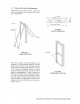
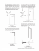
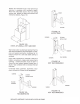
D. TYPICAL INSTALLATION PROCEDURES Position frame in the correct location. Brace the frame as shown, Figure 4. Do not brace in the direction of intended wall. 2x8 RACE FIGURE 5 WOOD SPREADER FIGURE 4 SPREADERS FRAME BRACING With frame in position, install the temporary wood spreaders. The wood spreader, Figure 5, must be square and no less than thick. Correct length is the door opening width between the jambs at the header. Cut clearance notches for frame stops.
At frames with jamb opening heights greater than 8 Al frames with sidelights where the sidelight sill 1t. (2438mm) or frame face dimensions less than intersects the door jamb near the strike, & is imperil in. (38mm), install an additional wood spreader. native that a wood spreader is located at this aerospace wood spreaders at a maximum of 38 in. Hon, Figure 8. {914mm} intervals between header and bottom of frame, Figure 7.
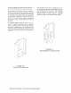
The installation contractor shall have a carpenter level and builder's square. Level the head by positioning the level to the head door rabbet, Figure 9. If necessary, adjust for high spots in floor by shimming under the jamb orifice anchor, Figure 13a. Equalize them through an adjustable floor anchor, if specified, Figure 13b. Note, for labeled openings the maximum floor clearance is 3/4 in. (19mm) / LEVEL FIGURE 9 LEVELING THE HEAD With builder's square, check frame for squareness.
Once the installer has ensured that the frame is in the correct position, anchor the jamb to the floor. Floor Anchors: The fixed floor anchor is welded to the base of the jamb, typically secured to the floor by mechanical fasteners, providing solid anchorage for the base of each jamb, Figure 13a.
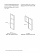
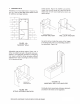
1. MASONRY WALLS Installation of a hollow metal frame in masonry, Figure 14a. Refer to HMM 820 Hollow Metal Frames for additional anchorage methods. SPREADERS. FIGURE 14A MASONRY WALL Adjustable strap-and-stirrup anchor, Figure 14b. A stirrup is welded to the back of the jamb, and a perforated or corrugated strap provides for embedding into masonry joints. The stirrup provides sufficient adjustment for masonry coursing as well as access for full grouting of jambs.
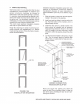
2. STEEL STUD WALLS installation of a hollow metal frame in steel stud wall, Figure 15a. Refer to HMM 820 Hollow Metal Frames for additional anchorage methods. CEILING RUNNER HEADER STUD / zl Jams §STUDS FLOOD RUNNER FIGURE 15A STEEL STUD WALL FIGURE 15B ZEE SHAPED STEEL STUD ANCHOR Zee shaped anchor, Figure 15b, is welded to both rabbets inside the jamb.
Position the vertical steel studs in the frame throat opening in accordance with architect's details. Attach the vertical steel studs to floor and ceiling runners and fasten to the steel stud anchors with mechanical fasteners, Figure 15d. FIGURE 15D STEEL STUD WALL WITH ANCHOR Wall Construction: It is extremely important that the steel stud manufacturer's recommendation on thickness and general construction technique be fob lowed to ensure that a solid and stable opening is achieved.
5. COMPLETED DRYWALL Wall Construction: It is very important that the stud manufacturer's recommendation on thickness and general construction technique be follows to ensure that & solid and stable opening is achieved. For example, double studding at the opening is necessary; the header stud must be the same width as the jamb stud. It is particularly important that the overlapping of vertical and horizontal steel studs be avoided since this produces oversize walls.
Attach the base anchor to the stud or floor channel at the base of the wall. The base anchor is usually a strap of metal, provided ether welded or loose at each side of the jamb at the bottom with holes punched for balls or screws, Figure 19c. FIGURE 19C SLIP-ON DRY WALL BASE ANCHOR Compression Anchor, Figure 19d. An adjustable compression device is normally located near the top of each jamb. This anchor is used on slip-on dry wall frames and in conjunction with slip-on dry wall base anchors.
PART 4 HANGING OF DOORS A. GENERAL it is the responsibility of the installer to hang all doors and install all hardware prior to finish painting. Doors shall be reinforced, drilled and tapped at the factory for templates mortise hardware only, in accordance with the approved hardware schedule and templates provided by the hardware supplier.
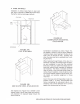
USE HINGE SHIMS TO ADJUST DOOR CLEARANCE HINGE HINGE FIGURE 21 SHIMMING TO INCREASE CLEARANCE AT HINGE EDGE Using shim A only, door will be relocated in direction of arrow 8. Using shim B only, both door and center line of hinge barrel will move in direction of arrow S. Using both shims A and B will move the door further in direction of arrow $ than by using either A or B alone, and hinge barrel will be relocated just as using B alone.
Painting Hollow Metal Products Hollow metal doors, frames, and related products are fabricated from hot-rolled, cold-rolled, Zing-costed, or stainless steel. Stainless is typically not painted and therefore not referred to in this tech note. Hot and cold rolled steel are supplied either dry or oiled and require treatment prior to painting. Zinc coated steel is dither galvanized or galvanized.