
User Manual
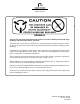


Table Of Contents
- ProTec AIS Installation & Operation Manual
- Return Material Policy
- Return of Material Under Warranty
- Table of Contents
- List of Figures
- Figure 1-1 AIS Transponder
- Figure 2-1 AIS Transponder
- Figure 2-2 NAV Display Screens
- Figure 2-3 Own Ship Data Display
- Figure 2-4 System Configuration Screen
- Figure 2-5 Vessel Data Setup
- Figure 2-6 Channel Management Settings Screen
- Figure 2-7 Antenna Position Screen
- Figure 2-8 Antenna Position Measurements
- Figure 2-9 Safety Text Message
- Figure 2-10 Safety Text Review Screen
- Figure 2-11 Password Entry Screen
- Figure 2-12 Password Change Screen
- Figure 2-13 System Alert Screen
- Figure 2-14 Alarm Status Screen
- Figure 2-15 Down-Time Log Screen
- Figure 3-1 AIS Transponder Interconnection Diagram
- Figure 3-2 AIS Transponder O&D Drawing with Optional Trunion Bracket
- Figure 3-3 AIS Transponder O&D Drawing
- Figure 3-4 AIS Transponder Power Cable
- Figure 3-5 Pilot Port Cable
- Figure 3-6 AIS Transponder IEC Cable
- Figure 3-7 IEC Cable Interconnect Diagram
- Figure 3-8 IEC Cable External Wiring Diagram
- Figure 3-9 AIS Transponder Antenna Diagram
- Figure 3-10 AIS Transponder Rear View
- Figure 3-11 AIS Transponder MKD
- Figure 3-12 System Configuration Screen
- Figure 3-13 Vessel Data Setup
- Figure 3-14 Antenna Position
- Figure 3-15 Calculating Antenna Position
- Figure 3-16 Transponder Interconnection Diagram
- List of Tables
- Table 1-1 AIS Parts List
- Table 1-2 Pilot System High-Speed Input Data Formats
- Table 1-3 Pilot System High-Speed Output Data Formats
- Table 1-4 Long Range Input Data and Formats
- Table 1-5 Long Range Output Data and Formats
- Table 1-6 Sensor Input Data and Formats
- Table 2-1 Vessel Type Codes
- Table 2-2 Password Type Menu Screen Access
- Table 3-1 Data Channels
- Table 3-2 IEC Cable and Junction Box Pinouts
- Table 3-3 Vessel Type Codes
- Section 1. AIS Introduction
- Section 2. AIS Operation
- Section 3. AIS Installation

Marine Systems
Aviation Recorders
Rev. 02 Page iii
July 29/03
Automatic Identification System
GENERAL
This product and related documentation must be reviewed for familiarization with safety
markings and instructions before operation.
This board was constructed in an ESD (electro–static discharge) protected environment. This is
because most of the semiconductor devices used in this board are susceptible to damage by static
discharge.
Depending on the magnitude of the charge, device substrates can be punctured or destroyed by
contact or mere proximity of a static charge. The results can cause degradation of device perfor-
mance, early failure, or immediate destruction.
These charges are generated in numerous ways such as simple contact, separation of materials,
and normal motions of persons working with static sensitive devices.
When handling or servicing equipment containing static sensitive devices, adequate precautions
must be taken to prevent device damage or destruction.
Only those who are thoroughly familiar with industry accepted techniques for handling static sen-
sitive devices should attempt to service circuitry with these devices.
In all instances, measures must be taken to prevent static charge build–up on work surfaces and
persons handling the devices.