
User Manual
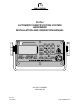


Table Of Contents
- ProTec AIS Installation & Operation Manual
- Return Material Policy
- Return of Material Under Warranty
- Table of Contents
- List of Figures
- Figure 1-1 AIS Transponder
- Figure 2-1 AIS Transponder
- Figure 2-2 NAV Display Screens
- Figure 2-3 Own Ship Data Display
- Figure 2-4 System Configuration Screen
- Figure 2-5 Vessel Data Setup
- Figure 2-6 Channel Management Settings Screen
- Figure 2-7 Antenna Position Screen
- Figure 2-8 Antenna Position Measurements
- Figure 2-9 Safety Text Message
- Figure 2-10 Safety Text Review Screen
- Figure 2-11 Password Entry Screen
- Figure 2-12 Password Change Screen
- Figure 2-13 System Alert Screen
- Figure 2-14 Alarm Status Screen
- Figure 2-15 Down-Time Log Screen
- Figure 3-1 AIS Transponder Interconnection Diagram
- Figure 3-2 AIS Transponder O&D Drawing with Optional Trunion Bracket
- Figure 3-3 AIS Transponder O&D Drawing
- Figure 3-4 AIS Transponder Power Cable
- Figure 3-5 Pilot Port Cable
- Figure 3-6 AIS Transponder IEC Cable
- Figure 3-7 IEC Cable Interconnect Diagram
- Figure 3-8 IEC Cable External Wiring Diagram
- Figure 3-9 AIS Transponder Antenna Diagram
- Figure 3-10 AIS Transponder Rear View
- Figure 3-11 AIS Transponder MKD
- Figure 3-12 System Configuration Screen
- Figure 3-13 Vessel Data Setup
- Figure 3-14 Antenna Position
- Figure 3-15 Calculating Antenna Position
- Figure 3-16 Transponder Interconnection Diagram
- List of Tables
- Table 1-1 AIS Parts List
- Table 1-2 Pilot System High-Speed Input Data Formats
- Table 1-3 Pilot System High-Speed Output Data Formats
- Table 1-4 Long Range Input Data and Formats
- Table 1-5 Long Range Output Data and Formats
- Table 1-6 Sensor Input Data and Formats
- Table 2-1 Vessel Type Codes
- Table 2-2 Password Type Menu Screen Access
- Table 3-1 Data Channels
- Table 3-2 IEC Cable and Junction Box Pinouts
- Table 3-3 Vessel Type Codes
- Section 1. AIS Introduction
- Section 2. AIS Operation
- Section 3. AIS Installation

Marine Systems
Aviation Recorders
Rev. 02 Page viii
July 29/03
Automatic Identification System
TABLE OF CONTENTS
(Continued)
SUBJECT/DESCRIPTION PAGE
SECTION 2 -- ProTec AIS Operation
2.1. Operation 2--3................................................................
2.1.1. Minimum Keyboard Display 2--3................................................
2.1.1.1Power/Dim Control 2--4........................................................
2.1.1.2Liquid Crystal Display 2--4.....................................................
2.1.1.3Key Pad 2--4.................................................................
2.1.1.4Pilot Port 2--4................................................................
2.1.2. Keypad Description 2--4.......................................................
2.1.3. Data Display Screens 2--6.....................................................
2.1.4. Data Entry Screens 2--8.......................................................
2.1.4.1Vessel Data Setup 2--9........................................................
2.1.4.2Channel Management 2--11....................................................
2.1.4.3Antenna Position 2--12........................................................
2.1.4.4Text Messaging 2--13.........................................................
2.1.4.5Password Entry 2--15.........................................................
2.1.4.6Change Password 2--16.......................................................
2.1.4.7System Alert Screen 2--17.....................................................
2.1.4.8Alarm Status 2--17............................................................
2.1.4.9Down--Time Log 2--18.........................................................
SECTION 3 -- ProTec AIS Installation
3.1. Installation 3--3...............................................................
3.1.1. Transponder 3--4.............................................................
3.1.2. Connecting the IEC Data Interface Cable 3--9....................................
3.1.2.1Data Channels 3--9...........................................................
3.1.2.2Data Cable 3--10.............................................................
3.1.2.3Terminal Block 3--13..........................................................
3.1.3. Installing the VHF Antenna 3--15...............................................
3.1.4. Installing the GPS Antenna 3--16...............................................
3.1.5. PowerUp and Configuration 3--19...............................................